Forces — Print · Physical Science: Matter, Forces & Energy, Grade 8
Model balanced forces, gravity, friction, electric and magnetic interactions, and fluid pressure.
Printable chapter lessons and review.
Balanced & Unbalanced Forces
Learning goals
- I can find the net force on an object from two or more forces.
- I can predict whether an object's motion will change based on whether forces are balanced or unbalanced.
Readings for this unit
Before this unit
Add forces with direction and distinguish force from motion.
Use three teaching sessions of about 40–45 minutes: first observe the phenomenon, draft a model and study Parts 1–2; next explain Parts 3–4 with the figures and evidence; then work the application, examples, practice, model revision and exit check. Divide any difficult part into smaller steps and revisit after feedback. Investigations, review and quizzes have separate sessions. Study the four visual parts across the scheduled sessions, then use the illustrated worked case and independent transfer questions. Extend or revisit a session when the learner cannot explain the figure; completion time is a proposed allocation, not a mastery guarantee.
Start with something to explain
What would explain the observations in balanced & unbalanced forces?
Illustrative evidence case. A supplied cart moves right steadily while forces are 5 N right and 5 N left. A later interval has 7 N right and 3 N left.
Notice and wonder
Could the top cart be moving right? Write two observations from the supplied record without guessing their cause. Include a quantity and its unit when given. An observation is what was recorded; an inference is what you think explains it.
Write one question about why the pattern occurs and one question about a comparison that could distinguish competing explanations. A testable question identifies what could be observed or measured.
Your first model
Before reading the model answer, sketch the named objects or particles and label what you think changes. Find the horizontal net force in both intervals and explain which interval changes velocity. Distinguish force from motion direction. Keep this first version so you can compare it with your later explanation.
Build the language from the idea
- net force
- The overall force on an object after combining all individual forces, accounting for direction.
- balanced forces
- Forces that combine to a net force of zero, so motion doesn't change.
- unbalanced forces
- Forces that combine to a net force that isn't zero, causing acceleration.
- model
- A representation that explains selected features and makes predictions; it leaves other details out.
- evidence
- Relevant observations or records used to support or challenge a claim.
- system boundary
- The chosen limit separating the objects being studied from their surroundings.
- assumption
- A condition taken as true for a model or calculation and needing to be checked against the case.
In the real world, objects almost never feel just a single force. Right now, gravity is pulling this book down, the table is pushing it up, and if you slid it, friction would drag against it too. What actually determines how an object moves isn't any one of those forces alone, but the net force — the single overall force you get after combining all of them, carefully accounting for direction. Forces pointing the same way add together; forces pointing in opposite directions partly or fully cancel.
When all the forces on an object cancel out to a net force of zero, we say the forces are balanced. A balanced object's motion doesn't change one bit. If it was sitting still, it stays still; if it was already gliding along, it keeps gliding at the same steady velocity. That's Newton's first law in action — no net force means no change in motion. A book resting on a table is the classic case: gravity pulls it down, the table pushes up with an equal force, and the two perfectly balance.
When the forces don't cancel — when there's some net force left over — the forces are unbalanced, and now the object's motion has to change. It accelerates in the direction of that leftover net force, speeding up, slowing down, or changing direction. Push a shopping cart harder than friction pushes back, and it rolls forward faster and faster. The bigger the unbalanced net force, the greater the acceleration it produces.
Working out the net force is mostly careful arithmetic with direction. Two forces in the same direction simply add: a 40 N push plus another 40 N push the same way is 80 N. Two forces in opposite directions subtract, and the net force points the way the larger one was pointing: 60 N to the right against 20 N to the left leaves 40 N to the right. Watch out for a common misconception here — an object moving at a steady speed does NOT need a net force to keep going. Constant velocity actually means the forces are balanced, exactly like an object standing still.
This single question — is the net force zero or not? — lets you predict what will happen to almost anything. A tug-of-war rope stays put while both teams pull equally hard, then suddenly lurches the instant one side gains an edge and the forces become unbalanced. From a car cruising at a constant speed (balanced) to a rocket blasting upward (wildly unbalanced), reading the net force tells you whether an object's motion will hold steady or change.
Choose one object and draw only the forces acting on it. Opposite equal arrows give zero net force. The object can then remain still or move in a straight line at constant velocity; balanced forces do not require zero speed.
Unbalanced forces change velocity, which can mean changing speed, direction or both. A turn at constant speed still involves acceleration. To predict the change, add forces as directional quantities rather than adding every magnitude as positive.
If a book rests on a table, the table's upward force balances the Earth's downward force on the book. Those two forces act on the same book and are not a third-law pair. Third-law forces act on different objects and therefore cannot cancel in one object's force diagram.
Build your understanding
Where this fits
This unit helps answer the chapter question: How can forces explain stability and changes in motion? Keep a notebook table with the question, evidence, explanation and one unresolved issue. Revise a previous model only when you can name the new evidence or idea that changes it.
Use three teaching sessions of about 40–45 minutes: first observe the phenomenon, draft a model and study Parts 1–2; next explain Parts 3–4 with the figures and evidence; then work the application, examples, practice, model revision and exit check. Divide any difficult part into smaller steps and revisit after feedback. Investigations, review and quizzes have separate sessions.
Part 1 · List forces acting on one object
Choose one object and draw arrows for external forces acting on it. Label the source of each force and its direction. Include pushes, pulls, friction, gravity, and support forces where relevant. A force diagram represents interactions, not a trail showing where the object has already traveled.
Read the visual model
Why does a force diagram need a named object?
Visual reasoning — after your attempt
Forces acting on different objects cannot be combined to find the net force on one object. Naming the object keeps the interactions and arrows consistent.
For a book resting on a table, Earth pulls down and the table pushes up. Draw both arrows on the book. Do not put the book’s downward push on the table in the book’s own force diagram; that force acts on the table.
Pause and explain
Why does a force diagram need a named object?
Check your reasoning after answering
Forces acting on different objects cannot be combined to find the net force on one object. Naming the object keeps the interactions and arrows consistent.
Part 2 · Find the net force along a line
Net force is the combined external force on the chosen object. In one dimension, forces in opposite directions subtract. Equal opposite forces give zero net force along that direction. Zero net force means zero acceleration, not necessarily zero velocity. Use direction words with the result.
Read the visual model
Choose the receiver before adding arrows. A sign records direction along the chosen line. Net force is the combined result of the real forces, not an extra push that exists in addition to them.
If the left force becomes 12 N while the right stays 10 N, what is the new net force and direction?
Visual reasoning — after your attempt
10−12 = −2 N with right positive: 2 N left. That predicts leftward acceleration, not necessarily leftward current velocity.
A cart experiences 8 N right and 3 N left, giving 5 N right. If the forces were 8 N each, the net force would be zero; a cart already moving could continue at constant velocity in the ideal model.
Pause and explain
Can balanced forces act on an object that is moving?
Check your reasoning after answering
Yes. With zero net force its velocity does not change. It can remain at rest or continue moving at constant speed in a straight line.
Part 3 · Separate velocity direction from acceleration direction
An unbalanced force changes velocity. If force acts opposite current motion, speed can decrease; if force acts in the same direction, speed can increase. If force changes direction relative to motion, the path can bend. The net-force arrow alone does not specify the object’s current velocity.
Read the visual model
Does a leftward net force prove the cart is already moving left?
Visual reasoning — after your attempt
No. It specifies leftward acceleration. A right-moving cart could be slowing, and a resting cart could begin moving left.
A cart moving right while experiencing a leftward net force initially slows. It does not instantly move left. A motion arrow and a force arrow answer different questions and should have different labels.
Pause and explain
Does a leftward net force prove the cart is already moving left?
Check your reasoning after answering
No. It specifies leftward acceleration. A right-moving cart could be slowing, and a resting cart could begin moving left.
Part 4 · Use evidence to revise an incomplete diagram
If measured velocity changes, a zero-net-force diagram is incomplete or the chosen model has failed. Look for omitted friction, air resistance, or a push that changes over time. A slow or stationary appearance is not sufficient evidence of exact balance; use observations over a measured interval.
Read the visual model
A mismatch can expose a missing force or a method problem. Revise the diagram with a named, testable interaction rather than inventing an unexplained arrow just to make the arithmetic match.
Why is a diagram containing only the 6 N push incomplete for these records? What further measurement could test the revision?
Visual reasoning — after your attempt
It predicts 3 m/s² rather than the supplied 2 m/s². Measure or investigate opposing resistance, while also checking mass and acceleration measurement uncertainty.
A toy car slows after the hand releases it. The hand no longer supplies a forward push, while rolling resistance and air resistance can act against motion. Include these interactions before deciding the first law was contradicted.
Pause and explain
What does slowing motion suggest about a zero-net-force claim?
Check your reasoning after answering
Slowing is a change in velocity, so the zero-net-force claim needs revision. Identify interactions that can provide the nonzero net force.
Apply the whole unit · Explain a braking cart
Illustrative horizontal forces on a cart moving right: pull 6 N right and resistance 10 N left. Vertical support and weight balance. In a second trial, pull and resistance are both 6 N.
Your task
Draw both force diagrams, calculate horizontal net forces, and predict how the rightward velocity initially changes. Explain why neither diagram alone establishes the starting speed.
What your response should show
- Use the supplied observations and measurements accurately; include units where needed.
- Explain the science behind your answer, rather than giving only a number or label.
- Show a labeled model, calculation, or evidence comparison as requested.
- State an assumption or limitation and suggest a useful next measurement.
Response guidance — after your attempt
First trial: net force 4 N left, giving leftward acceleration and initially slowing rightward motion. Second trial: zero horizontal net force, so rightward velocity stays constant in the model. Equal vertical forces give no vertical acceleration. Starting speed requires motion information; it is not determined by force balance alone.
Scientific references and adapted teaching resources
- OpenSciEd 8.1 Contact Forces — public unit overview
- OpenSciEd 8.3 Forces at a Distance — public unit overview
- OpenSciEd instructional model — storyline routines
- Creative Commons Attribution 4.0 — middle-school material license
Parent / teacher teaching notes
Use distinct arrow colors for forces and motion. Ask acting on which object for every arrow. Revisit constant velocity versus rest before adding numerical acceleration. Adaptation credit: OpenSciEd middle-school teaching routines and public task structures by OpenSciEd, CC BY 4.0. This independent version adds original explanatory text, data and figures, terminology support and a home-study schedule. It does not reproduce the complete teacher editions or their classroom validation.
The key idea
Add forces in the same direction, subtract forces in opposite directions; a net force of zero means balanced (no change in motion), otherwise the object accelerates.
Net Force
F net = F₁ + F₂ + …
add forces pointing in the same direction; subtract forces pointing in opposite directions, to find the overall net force.
Worked examples
Example 1
- Forces act in opposite directions, so subtract: 40 − 25 = 15.
- The larger force (40 N) was to the right, so the net force points right.
Example 2 · Worked application
- Choose right as positive.
- Net force=14−9=5 N right.
- A nonzero net force causes acceleration, which changes velocity.
Opposite directions require subtraction, not addition.
Example 3
- Forces act in opposite directions (down vs. up), so subtract: 10 − 10 = 0.
- A net force of zero means the forces are balanced.
Example 4
- Choose right as positive; add 14+(−9)=5 N.
- The acceleration is toward the right, regardless of the cart's initial motion.
Example 5 · Find and fix the mistake
- Test the claim against the stated conditions: Opposite directions require subtraction, not addition.
- Zero net force means no acceleration. An object can continue at constant velocity.
Opposite directions require subtraction, not addition.
Example 6 · Interpret the visual model
- Identify the represented objects, axes, labeled quantities and stated conditions before choosing a rule.
- Choose the receiver before adding arrows. A sign records direction along the chosen line. Net force is the combined result of the real forces, not an extra push that exists in addition to them.
- 10−12 = −2 N with right positive: 2 N left. That predicts leftward acceleration, not necessarily leftward current velocity.
Keep the model’s stated limits explicit: The two horizontal forces on this one cart have a common stated scale. The net is 10−6 = 4 N right, shown as a separate summary. Do not count the net arrow as another interaction, and do not add a partner force acting on a different object. Vertical weight and support are omitted from this horizontal comparison.
Avoid these mistakes
- Zero net force means zero acceleration, not necessarily zero velocity.
Check your understanding
A cart experiences 14 N right and 9 N left. Find net force and describe the change in velocity.
Discuss the answer
5 N right; velocity changes toward the right.
How can an object move while forces on it are balanced?
Discuss the answer
Choose one object and draw only the forces acting on it. Opposite equal arrows give zero net force. The object can then remain still or move in a straight line at constant velocity; balanced forces do not require zero speed. Unbalanced forces change velocity, which can mean changing speed, direction or both. A turn at constant speed still involves acceleration. To predict the change, add forces as directional quantities rather than adding every magnitude as positive.
Return to the phenomenon
A supplied cart moves right steadily while forces are 5 N right and 5 N left. A later interval has 7 N right and 3 N left. Find the horizontal net force in both intervals and explain which interval changes velocity. Distinguish force from motion direction. Revise your first explanation using a named idea from the lesson. Mark the changed part and the evidence that supports it.
Compare explanations after your attempt
The initial net force is zero, consistent with the stated constant velocity. The later net force is 4 N right, causing acceleration to the right for the same cart. Zero net force permits steady motion rather than require rest; a force direction does not by itself give an instantaneous velocity.
What should we investigate next?
Which condition could be changed to test a remaining uncertainty in this explanation? State the predicted observation and what result would challenge your model.
Investigate, explain and revise
Use these tasks after the three teaching sessions as needed. Discuss an attempted explanation before opening response guidance; a matching sentence is less important than a supported mechanism.
Activity 1 · Explain the new evidence case
Use the visible scenario above, Parts 1–4 and your first notebook model. No outside reading or equipment is required.
Your task
A supplied cart moves right steadily while forces are 5 N right and 5 N left. A later interval has 7 N right and 3 N left. Find the horizontal net force in both intervals and explain which interval changes velocity. Distinguish force from motion direction. Write 100–150 words or give a labeled drawing with an equivalent oral explanation.
Success criteria
- Use two relevant stated records or conditions.
- Explain the mechanism rather than only repeat a definition.
- Label observation and inference.
- Name a changed model feature or a remaining uncertainty.
Hint
Read the stated boundary and conditions before selecting a relationship. The unit’s worked examples show intermediate steps.
Response guidance — discuss after your attempt
The initial net force is zero, consistent with the stated constant velocity. The later net force is 4 N right, causing acceleration to the right for the same cart. Zero net force permits steady motion rather than require rest; a force direction does not by itself give an instantaneous velocity.
Activity 2 · Read and extend the figure
Study the new labeled figure and its caption, then compare it with the associated teaching part.
Your task
Could the top cart be moving right? Explain what each important label represents. Add one missing feature that would be needed for a different question, and explain why the original figure leaves it out.
Success criteria
- Answer the figure question with its stated labels.
- Connect the visual representation to the scientific idea.
- Identify a specific limitation from the caption.
- Propose a useful change without misrepresenting supplied evidence.
Hint
Both rows diagram forces on the same chosen receiver, the cart. The first permits rest or constant velocity; the second changes velocity. Vertical forces are omitted for this horizontal comparison. Force arrows describe pushes, not the cart’s distance traveled or its current speed.
Response guidance — discuss after your attempt
Yes, at constant velocity in the stated simple model. Zero net force does not require zero velocity. Both rows diagram forces on the same chosen receiver, the cart. The first permits rest or constant velocity; the second changes velocity. Vertical forces are omitted for this horizontal comparison. Force arrows describe pushes, not the cart’s distance traveled or its current speed.
Words to know
- net force
- The overall force on an object after combining all individual forces, accounting for direction.
- balanced forces
- Forces that combine to a net force of zero, so motion doesn't change.
- unbalanced forces
- Forces that combine to a net force that isn't zero, causing acceleration.
- model
- A representation that explains selected features and makes predictions; it leaves other details out.
- evidence
- Relevant observations or records used to support or challenge a claim.
- system boundary
- The chosen limit separating the objects being studied from their surroundings.
- assumption
- A condition taken as true for a model or calculation and needing to be checked against the case.
When forces don't line up: combining forces at an angle
Adding forces is easy when they point along the same line — just add or subtract. But when two forces act at a right angle to each other, like a boat's engine pushing it forward while a current pushes it sideways, you combine them using the same Pythagorean theorem (a² + b² = c²) you use in geometry. A 3 N push east and a 4 N push north combine into a single net force of √(3² + 4²) = √25 = 5 N, angled diagonally between the two — physics and math turning out to be exactly the same tool.
Terminal velocity: when a falling object's forces finally balance
A skydiver jumping from a plane doesn't just keep speeding up forever — as speed increases, air resistance (drag) pushing upward grows stronger too, until it exactly equals the pull of gravity. At that point, net force becomes zero, and the skydiver falls at a constant, unchanging speed called terminal velocity — for a human in a typical belly-down position, that's about 195 km/h (54 m/s). It's a perfect real-world example of balanced forces: even though the skydiver is very much still moving, their forces are balanced and their velocity stops changing.
Cruising at 35,000 feet: an airplane in perfectly balanced flight
It's tempting to think that if an airplane's engines are running, it must be accelerating — but a plane cruising at a constant altitude and constant speed has perfectly balanced forces acting on it: lift balances weight (up vs. down), and engine thrust balances air drag (forward vs. backward). The engines work constantly not to speed the plane up, but simply to keep matching the drag trying to slow it down. This is the same principle as a car maintaining a steady highway speed — the engine isn't 'winning' against friction, just fighting it to a draw.
Free-body diagrams: the engineer's trick for tracking every force
When several forces act on an object at once, physicists and engineers draw a free-body diagram: a simplified sketch of just the object, with an arrow for every force acting on it, sized to show relative strength and pointed in the right direction. Bridge engineers use exactly this technique to make sure the combined forces of traffic, wind, and the bridge's own weight stay balanced by the strength of its cables and supports — an unbalanced design isn't just a physics homework mistake, it's a structure that could actually fail.
In the real world
Tug-of-war is a great example of unbalanced forces — the moment one side pulls harder, the rope and both teams accelerate that way.
Exit check
Could the top cart be moving right? Explain the relevant mechanism and one model limitation.
Check your explanation after answering
Yes, at constant velocity in the stated simple model. Zero net force does not require zero velocity. Both rows diagram forces on the same chosen receiver, the cart. The first permits rest or constant velocity; the second changes velocity. Vertical forces are omitted for this horizontal comparison. Force arrows describe pushes, not the cart’s distance traveled or its current speed.
Explain your reasoning without notes. If a key idea is missing, revisit the lesson and try again.
Interaction Pairs & Force Diagrams
Learning goals
- I can label each force’s source and receiver and keep interaction partners on separate diagrams.
- I can find a one-dimensional net force and distinguish it from velocity.
Readings for this unit
Before this unit
Review the earlier balanced/unbalanced forces unit. The visible language notes explain this unit’s quantities; then connect them to its concrete records and figure.
Use three teaching sessions of about 40–45 minutes: first observe the phenomenon, draft a model and study Parts 1–2; next explain Parts 3–4 with the figures and evidence; then work the application, examples, practice, model revision and exit check. Divide any difficult part into smaller steps and revisit after feedback. Investigations, review and quizzes have separate sessions. Study the four visual parts across the scheduled sessions, then use the illustrated worked case and independent transfer questions. Extend or revisit a session when the learner cannot explain the figure; completion time is a proposed allocation, not a mastery guarantee.
Start with something to explain
What would explain the observations in interaction pairs & force diagrams?
Illustrative evidence case. In an illustrative interaction a hand pushes a cart rightward with 8 N. Floor resistance on the cart is 3 N leftward.
Notice and wonder
With 3 N leftward friction, what is the cart’s horizontal net force? Write two observations from the supplied record without guessing their cause. Include a quantity and its unit when given. An observation is what was recorded; an inference is what you think explains it.
Write one question about why the pattern occurs and one question about a comparison that could distinguish competing explanations. A testable question identifies what could be observed or measured.
Your first model
Before reading the model answer, sketch the named objects or particles and label what you think changes. State the cart’s horizontal net force and the cart-on-hand force; explain why they differ. Keep this first version so you can compare it with your later explanation.
Build the language from the idea
- interaction
- Mutual influence between named objects.
- force diagram
- Representation of the forces acting on one chosen object.
- receiver
- Object on which a named force acts.
- normal force
- Contact support force perpendicular to a surface.
- net force
- Directional sum of forces on one object.
- model
- A representation that explains selected features and makes predictions; it leaves other details out.
- evidence
- Relevant observations or records used to support or challenge a claim.
- system boundary
- The chosen limit separating the objects being studied from their surroundings.
- assumption
- A condition taken as true for a model or calculation and needing to be checked against the case.
When a hand pushes a cart, the cart also pushes the hand. An interaction involves two objects affecting each other.
A force is a push or pull, and direction matters. A force diagram represents the forces acting on one chosen object; it is not a picture of every force in the room.
The length of an arrow can represent relative force size if a scale is stated. Begin with named objects and observations before adding arrows.
This prevents the common error of putting an equal-and-opposite interaction pair on the same object and concluding that all motion must be impossible.
An observation is what a person or instrument records. An inference is a proposed interpretation of those records. Keep the two separate: a graph can show a pattern while more than one mechanism might explain it. State the chosen system, or part of the world being studied, and its boundary before accounting for material or energy transfers.
Use each figure as a reasoning tool. Read its caption and labels, describe the pattern, then explain a cause. If the picture is schematic, use the stated numbers rather than measuring its printed size. Check whether its simplified conditions match the problem before applying a formula.
Build your understanding
Where this fits
This unit helps answer the chapter question: How can forces explain stability and changes in motion? Keep a notebook table with the question, evidence, explanation and one unresolved issue. Revise a previous model only when you can name the new evidence or idea that changes it.
Use three teaching sessions of about 40–45 minutes: first observe the phenomenon, draft a model and study Parts 1–2; next explain Parts 3–4 with the figures and evidence; then work the application, examples, practice, model revision and exit check. Divide any difficult part into smaller steps and revisit after feedback. Investigations, review and quizzes have separate sessions.
Part 1 · Name the object receiving each force
Write forces as “force of A on B.” B is the receiver and belongs in the diagram being constructed. Gravity from Earth, support from a table and a push from a hand come from different interactions. The support force is often called the normal force; normal here means perpendicular to the surface.
Read the visual model
Which receiver belongs in a cart diagram?
Visual reasoning — after your attempt
The cart. Forces exerted on the table or on Earth belong in separate diagrams, even though they are connected interactions.
For a cart resting on a horizontal table, draw Earth-on-cart downward and table-on-cart upward. The table is not doing nothing merely because the cart is still; it deforms slightly and supplies support.
Pause and explain
Which receiver belongs in a cart diagram?
Check your reasoning after answering
The cart. Forces exerted on the table or on Earth belong in separate diagrams, even though they are connected interactions.
Part 2 · Keep an interaction pair on separate objects
Newton’s third law describes a pair: A-on-B and B-on-A are equal in size and opposite in direction during the same interaction. They act on different objects. Equal interaction forces do not imply equal changes in motion when the object masses differ.
Read the visual model
Read a force name as source-on-receiver. That naming convention makes the third-law pair explicit. Balanced forces on one receiver are a different comparison from this equal-and-opposite pair between two receivers.
Which of these arrows belongs on the cart’s free-body diagram? Where does the other belong?
Visual reasoning — after your attempt
Only the hand-on-cart arrow belongs on the cart’s diagram. The equal cart-on-hand partner belongs on the hand’s diagram.
A person pushes a cart rightward. The cart pushes the person leftward at the same instant. The cart’s diagram contains the person-on-cart force; the person’s diagram contains the cart-on-person force.
Pause and explain
Why do the two forces not cancel in the cart diagram?
Check your reasoning after answering
Only one acts on the cart. Adding a force on the person to the forces on the cart mixes receivers and gives an invalid net force.
Part 3 · Find the net force on one receiver
Net force means the directional combination of forces on the chosen object. Along one line, choose a positive direction and subtract opposing forces. Balanced means the net force is zero, which allows rest or constant velocity; it does not require absence of forces.
Read the visual model
A free-body diagram includes forces on the chosen object and the sources of those forces. Then compare directions to determine net force. To predict speeding up or slowing down, also identify the current velocity.
If the cart is moving left when these forces act, what can happen to its speed initially?
Visual reasoning — after your attempt
It initially slows because rightward acceleration opposes its leftward velocity. It can later stop and reverse if the same net force persists.
A cart has a 6 N rightward push and a 2 N leftward resistive force, so its horizontal net force is 4 N rightward. Newton, written N, is the force unit. Its vertical support and weight can balance separately.
Pause and explain
Does a 4 N horizontal net force require an unbalanced vertical force?
Check your reasoning after answering
No. Horizontal and vertical comparisons are separate in this simple model. The vertical forces may balance while horizontal motion changes.
Part 4 · Test what a diagram predicts
A model should connect arrows with observed changes in motion and state missing information. A nonzero net force predicts acceleration, a change in velocity, rather than a particular speed without time and mass information. A force arrow is not automatically a velocity arrow.
Read the visual model
A prediction connects one representation to another. Translate arrows into net force, net force into acceleration, and acceleration into the slope of a velocity–time record. Check the assumptions about mass and the reference frame.
Would a claimed zero-net-force diagram agree with this graph? Explain the evidence rather than just saying no.
Visual reasoning — after your attempt
No. The velocity changes by 6 m/s in 3 s, so the supplied mass requires a nonzero net force of 4 N right. Zero net force would predict constant velocity in this model.
A cart moving rightward can have a leftward net force while slowing. Draw the motion arrow and force arrows with different labels. Use before-and-after position or speed records to check the interpretation.
Pause and explain
If a cart is moving right, must its net force point right?
Check your reasoning after answering
No. It can be slowing under a leftward net force or moving steadily with zero net force. Motion direction and net-force direction are different quantities.
Apply the whole unit · Two diagrams for one push
Illustrative case for analysis, not measurements collected by the learner. In an illustrative interaction a hand pushes a cart rightward with 8 N. Floor resistance on the cart is 3 N leftward.
Your task
State the cart’s horizontal net force and the cart-on-hand force; explain why they differ. Use the supplied conditions, show intermediate reasoning and distinguish the supported conclusion from a broader claim.
What your response should show
- Use the specified quantities and units.
- Explain an intermediate step or comparison.
- Connect the pattern to the physical mechanism.
- State an assumption or limitation.
Response guidance — after your attempt
Choose the cart as receiver for the net-force sum.
Subtract 3 N left resistance from 8 N right push: net force is 5 N right.
For the hand–cart interaction, the cart-on-hand partner is 8 N left; its receiver is the hand.
Do not subtract the partner on the hand when adding forces on the cart.
The cart’s net force is 8−3=5 N rightward. The cart pushes the hand with 8 N leftward as the partner of the hand-on-cart interaction. The 3 N floor force belongs to another interaction. Net force on the cart and the pair force on the hand answer different questions.
Scientific references and adapted teaching resources
- OpenSciEd 8.1 Contact Forces — public unit overview
- OpenSciEd 8.3 Forces at a Distance — public unit overview
- OpenSciEd instructional model — storyline routines
- Creative Commons Attribution 4.0 — middle-school material license
Parent / teacher teaching notes
Ask the learner to describe the phenomenon before naming a formula. Discuss each checkpoint after an attempt. Use the supplied records when equipment is unavailable and label them illustrative rather than actual measurements. The final explanation should identify a mechanism and a limit, with different defensible wording accepted. Adaptation credit: OpenSciEd middle-school teaching routines and public task structures by OpenSciEd, CC BY 4.0. This independent version adds original explanatory text, data and figures, terminology support and a home-study schedule. It does not reproduce the complete teacher editions or their classroom validation.
The key idea
Interaction partners act on different objects; acceleration depends on the net force on each object separately. The cart’s net force is 8−3=5 N rightward.
Worked examples
Example 1 · Build the first reasoning step
- Identify what the question asks and what the stated observation establishes.
- The cart. Forces exerted on the table or on Earth belong in separate diagrams, even though they are connected interactions.
Example 2 · Two diagrams for one push
- Choose the cart as receiver for the net-force sum.
- Subtract 3 N left resistance from 8 N right push: net force is 5 N right.
- For the hand–cart interaction, the cart-on-hand partner is 8 N left; its receiver is the hand.
- Do not subtract the partner on the hand when adding forces on the cart.
Explain why each stated condition matters.
Example 3 · Transfer to a different condition
- Identify the changed condition.
- No. Both act on the book. Their partners act on Earth and on the table respectively. They may balance on the book without being the two sides of one interaction.
Example 4 · Find and fix the mistake
- Distinguish what is observed from what is inferred.
- Interaction partners act on different objects; acceleration depends on the net force on each object separately.
Compare the claim with the stated observations and model assumptions.
Example 5 · Interpret the visual model
- Identify the represented objects, axes, labeled quantities and stated conditions before choosing a rule.
- Read a force name as source-on-receiver. That naming convention makes the third-law pair explicit. Balanced forces on one receiver are a different comparison from this equal-and-opposite pair between two receivers.
- Only the hand-on-cart arrow belongs on the cart’s diagram. The equal cart-on-hand partner belongs on the hand’s diagram.
Keep the model’s stated limits explicit: The red arrow represents the hand’s rightward force on the cart. The blue arrow is the cart’s equal leftward force on the hand. They act on different receivers, so they cannot be canceled within the cart’s own force sum. Other forces on each receiver still matter, and equal interaction forces do not guarantee equal acceleration.
Avoid these mistakes
- Interaction partners act on different objects; acceleration depends on the net force on each object separately.
- Do not treat a schematic drawing as a scale measurement or a universal guarantee.
- Keep the stated comparison conditions and measurement boundary explicit.
- A correct numerical result needs units and an explanation of its meaning.
Check your understanding
Which receiver belongs in a cart diagram?
Discuss the answer
The cart. Forces exerted on the table or on Earth belong in separate diagrams, even though they are connected interactions.
Why do the two forces not cancel in the cart diagram?
Discuss the answer
Only one acts on the cart. Adding a force on the person to the forces on the cart mixes receivers and gives an invalid net force.
Does a 4 N horizontal net force require an unbalanced vertical force?
Discuss the answer
No. Horizontal and vertical comparisons are separate in this simple model. The vertical forces may balance while horizontal motion changes.
If a cart is moving right, must its net force point right?
Discuss the answer
No. It can be slowing under a leftward net force or moving steadily with zero net force. Motion direction and net-force direction are different quantities.
Return to the phenomenon
In an illustrative interaction a hand pushes a cart rightward with 8 N. Floor resistance on the cart is 3 N leftward. State the cart’s horizontal net force and the cart-on-hand force; explain why they differ. Revise your first explanation using a named idea from the lesson. Mark the changed part and the evidence that supports it.
Compare explanations after your attempt
The cart’s net force is 8−3=5 N rightward. The cart pushes the hand with 8 N leftward as the partner of the hand-on-cart interaction. The 3 N floor force belongs to another interaction. Net force on the cart and the pair force on the hand answer different questions.
What should we investigate next?
Which condition could be changed to test a remaining uncertainty in this explanation? State the predicted observation and what result would challenge your model.
Investigate, explain and revise
Use these tasks after the three teaching sessions as needed. Discuss an attempted explanation before opening response guidance; a matching sentence is less important than a supported mechanism.
Activity 1 · Explain the new evidence case
Use the visible scenario above, Parts 1–4 and your first notebook model. No outside reading or equipment is required.
Your task
In an illustrative interaction a hand pushes a cart rightward with 8 N. Floor resistance on the cart is 3 N leftward. State the cart’s horizontal net force and the cart-on-hand force; explain why they differ. Write 100–150 words or give a labeled drawing with an equivalent oral explanation.
Success criteria
- Use two relevant stated records or conditions.
- Explain the mechanism rather than only repeat a definition.
- Label observation and inference.
- Name a changed model feature or a remaining uncertainty.
Hint
Read the stated boundary and conditions before selecting a relationship. The unit’s worked examples show intermediate steps.
Response guidance — discuss after your attempt
The cart’s net force is 8−3=5 N rightward. The cart pushes the hand with 8 N leftward as the partner of the hand-on-cart interaction. The 3 N floor force belongs to another interaction. Net force on the cart and the pair force on the hand answer different questions.
Activity 2 · Read and extend the figure
Study the new labeled figure and its caption, then compare it with the associated teaching part.
Your task
With 3 N leftward friction, what is the cart’s horizontal net force? Explain what each important label represents. Add one missing feature that would be needed for a different question, and explain why the original figure leaves it out.
Success criteria
- Answer the figure question with its stated labels.
- Connect the visual representation to the scientific idea.
- Identify a specific limitation from the caption.
- Propose a useful change without misrepresenting supplied evidence.
Hint
These arrows represent the equal-size opposite-direction forces of one hand–cart interaction. Their receivers are different objects. A cart net-force diagram must include other forces on the cart, such as friction, rather than import the force acting on the hand. Distances and arrow lengths are schematic.
Response guidance — discuss after your attempt
8−3=5 N rightward. The cart-on-hand partner remains 8 N leftward; it is not the cart’s net force. These arrows represent the equal-size opposite-direction forces of one hand–cart interaction. Their receivers are different objects. A cart net-force diagram must include other forces on the cart, such as friction, rather than import the force acting on the hand. Distances and arrow lengths are schematic.
Words to know
- interaction
- Mutual influence between named objects.
- force diagram
- Representation of the forces acting on one chosen object.
- receiver
- Object on which a named force acts.
- normal force
- Contact support force perpendicular to a surface.
- net force
- Directional sum of forces on one object.
- model
- A representation that explains selected features and makes predictions; it leaves other details out.
- evidence
- Relevant observations or records used to support or challenge a claim.
- system boundary
- The chosen limit separating the objects being studied from their surroundings.
- assumption
- A condition taken as true for a model or calculation and needing to be checked against the case.
In the real world
In an illustrative interaction a hand pushes a cart rightward with 8 N. Floor resistance on the cart is 3 N leftward.
Exit check
With 3 N leftward friction, what is the cart’s horizontal net force? Explain the relevant mechanism and one model limitation.
Check your explanation after answering
8−3=5 N rightward. The cart-on-hand partner remains 8 N leftward; it is not the cart’s net force. These arrows represent the equal-size opposite-direction forces of one hand–cart interaction. Their receivers are different objects. A cart net-force diagram must include other forces on the cart, such as friction, rather than import the force acting on the hand. Distances and arrow lengths are schematic.
Explain your reasoning without notes. If a key idea is missing, revisit the lesson and try again.
Gravity & Friction
Learning goals
- I can describe how gravity depends on mass, and calculate weight using W = mg.
- I can describe how friction opposes motion and identify factors that change its strength.
- I can argue from mass/distance evidence and distinguish free fall from significant drag.
Readings for this unit
Before this unit
Distinguish mass from gravitational force.
Use three teaching sessions of about 40–45 minutes: first observe the phenomenon, draft a model and study Parts 1–2; next explain Parts 3–4 with the figures and evidence; then work the application, examples, practice, model revision and exit check. Divide any difficult part into smaller steps and revisit after feedback. Investigations, review and quizzes have separate sessions. Study the four visual parts across the scheduled sessions, then use the illustrated worked case and independent transfer questions. Extend or revisit a session when the learner cannot explain the figure; completion time is a proposed allocation, not a mastery guarantee.
Start with something to explain
What would explain the observations in gravity & friction?
Illustrative evidence case. An illustrative 2 kg object has weight 19.6 N using Earth g=9.8 N/kg and 3.2 N using a modeled Moon g=1.6 N/kg. Both trials use the same object. A released ball can still be rising while its acceleration points downward. The trajectory drawing shows the same downward acceleration on the way up, at the top, and on the way down. Use it to distinguish the direction of motion from the direction of change in motion.
Notice and wonder
Why does the object retain its mass on the Moon? Write two observations from the supplied record without guessing their cause. Include a quantity and its unit when given. An observation is what was recorded; an inference is what you think explains it.
Write one question about why the pattern occurs and one question about a comparison that could distinguish competing explanations. A testable question identifies what could be observed or measured.
Your first model
Before reading the model answer, sketch the named objects or particles and label what you think changes. Explain the mass and weight comparison, then identify a friction test that would isolate surface type. Keep this first version so you can compare it with your later explanation.
Build the language from the idea
- gravity
- An attractive force between any two objects with mass; bigger masses and closer distances create a stronger pull.
- weight
- The force of gravity on an object's mass, calculated as weight = mass × g (W = mg).
- mass
- The amount of matter in an object, measured in kilograms; it doesn't change no matter where the object is.
- friction
- A force that opposes motion between two surfaces in contact.
- air resistance
- A type of friction caused by air pushing against a moving object.
- model
- A representation that explains selected features and makes predictions; it leaves other details out.
- evidence
- Relevant observations or records used to support or challenge a claim.
- system boundary
- The chosen limit separating the objects being studied from their surroundings.
- assumption
- A condition taken as true for a model or calculation and needing to be checked against the case.
Gravity is an attractive interaction between objects with mass. Its strength depends on the masses and separation. Near Earth, the ideal free-fall acceleration is approximately 9.8 m/s² when air resistance is negligible. A heavier object has greater weight but also greater inertia, giving the same ideal acceleration. Different shapes can fall differently in air because drag affects their motion. State the model assumptions rather than claiming that every real falling object has identical acceleration.
That pull gives every object a weight, calculated as weight = mass × g, or W = mg, and measured in newtons (N) like any other force. It's tempting to treat weight and mass as the same thing, but they're genuinely different. Mass is the amount of matter packed into an object (measured in kilograms), and it never changes no matter where the object goes. Weight is the force of gravity acting on that mass, so it changes whenever gravity changes.
The Moon makes the difference vivid. An astronaut has the exact same mass on the Moon as on Earth — she's made of the same amount of matter either way. But the Moon is much smaller, so its gravity is only about a sixth as strong, and she therefore weighs only about a sixth as much. She could bound across the surface in giant leaps not because she lost any mass, but because the force pulling her down got weaker.
Friction resists relative sliding, or the tendency to slide, between contacting surfaces. It can depend on surface materials, microscopic contact interactions, normal force, and whether surfaces are already sliding. Surface roughness alone is not a universal predictor. Friction may oppose a sliding box’s motion, but static friction can provide the forward force that helps a person walk. Describe the contact and relative motion before assigning a friction arrow.
Air resistance is a specific kind of friction — the push of air against anything moving through it. It's the reason a feather drifts slowly to the floor while a rock plummets, even though gravity pulls on both. The feather's large surface area and tiny mass let air resistance hold it back far more, relative to its weight. This leads to a famous surprise: in a vacuum with no air at all, a feather and a rock dropped together actually hit the ground at the exact same instant — a result astronauts have demonstrated on the airless Moon.
Mass measures inertia and is measured in kilograms. Weight is gravitational force and is measured in newtons. Near Earth's surface weight is approximately mass×9.8 N/kg, although using 10 N/kg is suitable when a question says to approximate.
Friction depends on contact materials, surface conditions and the forces pressing surfaces together. It can slow sliding, but it also lets shoes grip the ground and tires push a road. Static friction can act without visible sliding.
Gravity acts without contact and depends on the masses and their separation. In everyday falling objects, air resistance can hide the simple gravitational pattern. Compare shapes and release conditions before assuming a heavier object always has a larger downward acceleration.
A thrown ball also keeps accelerating downward while it is rising. After it leaves the hand, gravity changes its vertical velocity; an initial horizontal velocity continues in an ideal model without drag. The trajectory is the ball’s curved path through space. At its highest point the vertical component of velocity is zero for an instant, while gravity and any horizontal component of velocity are still present. Study the labeled throw below before using the graphs.
Build your understanding
Where this fits
This unit helps answer the chapter question: How can forces explain stability and changes in motion? Keep a notebook table with the question, evidence, explanation and one unresolved issue. Revise a previous model only when you can name the new evidence or idea that changes it.
Use three teaching sessions of about 40–45 minutes: first observe the phenomenon, draft a model and study Parts 1–2; next explain Parts 3–4 with the figures and evidence; then work the application, examples, practice, model revision and exit check. Divide any difficult part into smaller steps and revisit after feedback. Investigations, review and quizzes have separate sessions.
Part 1 · Distinguish mass from gravitational force
Mass is measured in kilograms and relates to inertia. Weight is the gravitational force on an object, measured in newtons. Near Earth’s surface, the introductory model uses weight=mass×g with g approximately 9.8 N/kg or a supplied rounded value. Different locations can change weight without changing mass.
Read the visual model
What remains unchanged when the same object moves to a weaker gravitational field?
Visual reasoning — after your attempt
Its mass remains the same if no matter is added or lost. Its gravitational weight decreases because the local field is weaker.
A 2 kg object has weight about 19.6 N near Earth using 9.8 N/kg. On a location with weaker gravitational field, the same object retains 2 kg mass but has lower weight. State which quantity a scale reports.
Pause and explain
What remains unchanged when the same object moves to a weaker gravitational field?
Check your reasoning after answering
Its mass remains the same if no matter is added or lost. Its gravitational weight decreases because the local field is weaker.
Part 2 · Explain equal free-fall acceleration
A heavier object experiences a larger gravitational force near Earth, but also has more inertia. In the model neglecting air resistance, these increase together, giving the same acceleration g. Real falling motion may differ because drag depends on shape, size, speed, and surrounding air.
Read the visual model
Why does greater weight not automatically give greater ideal free-fall acceleration?
Visual reasoning — after your attempt
Greater mass also means greater resistance to acceleration. Since gravitational force is mg, force divided by mass gives g for each object when drag is neglected.
A flat sheet and a crumpled sheet of the same paper can fall differently in air despite similar mass. This compares the effect of shape and drag, not a rule that mass alone determines falling speed. Use supplied observations or a low safe drop.
Pause and explain
Why does greater weight not automatically give greater ideal free-fall acceleration?
Check your reasoning after answering
Greater mass also means greater resistance to acceleration. Since gravitational force is mg, force divided by mass gives g for each object when drag is neglected.
Part 3 · Identify what friction opposes
Friction at a contact resists relative slipping or the tendency to slip between surfaces. It can help a walker move forward because a shoe pushes backward against the ground and the ground provides forward static friction. Friction is not always opposite the overall travel direction of an object.
Read the visual model
Can friction help rather than prevent motion?
Visual reasoning — after your attempt
Yes. Static friction between a shoe and ground can provide forward force during walking. Its direction depends on the tendency of the surfaces to slip.
For a sliding box, friction usually acts against its sliding motion relative to the floor. For a driven wheel rolling without slipping, the contact force can have a different direction. Describe the contact motion before assigning the arrow.
Use the two contacts in the figure to test the slogan that friction always opposes motion. The sliding box has friction to the left because it slips right relative to the floor. The planted walking shoe has a tendency to slip backward relative to the ground, so static friction on the shoe can point forward. Static means the surfaces do not slide relative to each other at that contact, not that the entire person is motionless.
Pause and explain
Can friction help rather than prevent motion?
Check your reasoning after answering
Yes. Static friction between a shoe and ground can provide forward force during walking. Its direction depends on the tendency of the surfaces to slip.
Part 4 · Compare resistance with a controlled method
Surface type, normal force, lubrication, and motion conditions can affect friction. A comparison should keep other factors comparable and measure the relevant force or motion. The force needed to start sliding may differ from the force needed to maintain steady sliding. Do not assume one reading applies to every situation.
Read the visual model
Why must steady speed be stated when using a pull to estimate friction?
Visual reasoning — after your attempt
At steady straight-line speed the net force is zero, so the pull balances resistance in the stated model. During acceleration the pull need not equal friction.
Pull the same loaded sample at steady speed in supplied trials over two surfaces. Under the stated horizontal balanced-force conditions, the measured pull estimates sliding resistance. A pull during speeding up includes a net force and cannot be interpreted the same way.
Read the sliding-box graph as a motion record, not a picture of its path. The modeled speed falls 4 m/s each second during this interval. If right is positive, acceleration is −4 m/s². For mass 0.5 kg, the net horizontal force is −2 N; call that friction only when there are no other horizontal forces. A straight line here is an illustrative constant-resistance approximation, and must not be continued past the box coming to rest.
Pause and explain
Why must steady speed be stated when using a pull to estimate friction?
Check your reasoning after answering
At steady straight-line speed the net force is zero, so the pull balances resistance in the stated model. During acceleration the pull need not equal friction.
Gravity: masses, distance and free fall
A change of weight with location and a changing gravitational interaction answer related but different questions.
Gravity is an attractive interaction between objects with mass. Attractive means each object is pulled toward the other, with the interaction partner acting on the other receiver. Increasing one mass can increase the interaction; increasing separation generally weakens it for the simple two-object comparison. The evidence table changes one factor at a time. It is not a requirement to memorize a universal gravitation formula or calculate real planetary orbits here.
Near Earth, a falling object can be in free fall when gravity is the only significant force on it. A vacuum is a region with negligible material compared with ordinary air, so an ideal vacuum model removes air drag. Free fall can also be approximated in air when drag is small enough for the question. A heavier object has greater weight and greater inertia; these scale together, giving the same near-Earth acceleration when drag is negligible. A parachute or broad sheet changes drag and is not that simple comparison.
A satellite or a thrown object does not need gravity to vanish while moving. An inward force can continuously change direction, producing a curved path. In a stable simplified orbit, the object does not simply drop straight down because it already has sideways motion. Predicting an exact trajectory needs additional data and a more detailed model. The word stability refers to a persisting pattern under stated conditions, not an absence of forces or all objects being perfectly stationary.
Evidence to interpret
| Masses | Separation | Attractive force (relative units) |
|---|---|---|
| M and M | r | 8 |
| 2M and M | r | 16 |
| M and M | 2r | 2 |
Explain and apply
Use the table to construct a gravitational claim about mass and separation. Then explain why a feather and stone can fall differently in air without proving different ideal free-fall acceleration.
- Compare one changed factor at a time.
- Explain attraction and appropriate force receivers.
- Distinguish gravity-only motion from significant drag.
Reasoning and marking guidance — after your attempt
The force rises from 8 to 16 relative units when one mass doubles at fixed separation, and falls to 2 when separation doubles at the reference masses. These model comparisons support attractive, mass- and distance-dependent interaction under the stated conditions. Feather/stone differences in air also involve drag and inertia; an ideal negligible-drag comparison does not depend on mass in the same way. Separate receivers for the interaction pair and name the model limit.
A thrown ball: trajectory, gravity and graphs
A ball does not need an upward force to keep rising after release. Its existing upward velocity decreases as gravity accelerates it downward. We can connect the curved path to several time graphs without trigonometry.
A trajectory is the path an object follows through space. Break this throw into two simultaneous motions: a horizontal component and a vertical component. A component is the part in one chosen direction. Choose right and up as positive. The model starts at height 0 m with horizontal velocity 6 m/s and upward velocity 10 m/s; gravity gives vertical acceleration −10 m/s². The Earth value is rounded from about 9.8. We ignore air drag and spin and stop the model when the ball returns to its release height.
Think through equal half-second steps. Horizontal velocity stays 6 m/s, so horizontal position increases by 3 m each half-second. Vertical velocity changes by −5 m/s each half-second: +10, +5, 0, −5, −10. Height rises from 0 to 3.75 to 5 m, then falls to 3.75 and 0 m. These are model predictions, not measurements of a real ball. The acceleration does not switch direction at the top, and the hand exerts no continuing force after release.
The physical path has horizontal position on its horizontal axis and height on its vertical axis. The four time graphs instead all have time on the horizontal axis. Their shapes answer different questions. The slope of the horizontal-position graph is horizontal velocity; the slope of the height graph is vertical velocity. The slope of the vertical-velocity graph is vertical acceleration. At 1 s, height is maximum and vertical velocity is zero; horizontal velocity remains 6 m/s and vertical acceleration remains −10 m/s². Do not say that the ball has no velocity or no force at the top.
For a calculation extension, horizontal position x = 6t, vertical velocity vᵧ = 10−10t, and height y = 10t−5t², with t in seconds and the stated SI units. The symbol t² means t multiplied by itself. At 0.5 s, y = 10×0.5−5×0.25 = 3.75 m. At 1.5 s it is also 3.75 m, but the vertical velocities are opposite. The formulas summarize this ideal constant-acceleration model; they are not a rule for every real throw.
Compare a horizontal throw and a drop from the same height with the same zero initial vertical velocity. Without air drag, their vertical motions match even though one also moves sideways. Both reach the ground together. That conclusion does not compare a drop with a ball launched upward, since those have different initial vertical velocities. Changing only horizontal speed in our explorer changes the range but leaves the 2 s flight time and 5 m maximum height unchanged.
A real ball can experience drag opposite its motion and forces associated with spin. These can change the horizontal velocity, flight time and path. Our simplified model is useful because it isolates what gravity does; predictions must be checked against actual conditions. Two-dimensional motion here extends the one-dimensional motion required in the middle-school standard. Begin with arrows and the table; the algebra is an optional second pass, not a prerequisite for understanding why the ball curves.
Explore the throw
Predict first, then move the time slider. Compare the ball’s position, velocity and acceleration at the same instant. Change horizontal speed to test which parts of the motion change.
The labeled figures and supplied table below contain the complete model; the controls enhance it when JavaScript is available.
Evidence to interpret
| Time (s) | Horizontal position (m) | Height (m) | Horizontal velocity (m/s) | Vertical velocity (m/s) | Vertical acceleration (m/s²) |
|---|---|---|---|---|---|
| 0 | 0 | 0 | 6 | +10 | −10 |
| 0.5 | 3 | 3.75 | 6 | +5 | −10 |
| 1 | 6 | 5 | 6 | 0 | −10 |
| 1.5 | 9 | 3.75 | 6 | −5 | −10 |
| 2 | 12 | 0 | 6 | −10 | −10 |
Investigate or evaluate the supplied records
- Use the supplied no-drag records; predict the velocity and acceleration arrows before checking them. No throwing experiment is required.
- Read the axes of each graph and locate the same 0.5 s, 1 s and 1.5 s instants.
- Draw a prediction for horizontal speed 2 m/s with upward speed still 10 m/s. Then check the explorer or use x = 2t.
- Explain which predictions would be less reliable for a light object experiencing substantial air drag.
Explain and apply
At 0.5 s and 1.5 s the ball has the same height. Explain how its velocity differs while acceleration stays the same. Then predict the flight time, maximum height and horizontal range when only the starting horizontal speed changes from 6 to 2 m/s. Use the figures, graph axes and table in your explanation.
- Distinguish trajectory axes from time-graph axes and label velocity and acceleration arrows with directions.
- Use the two equal-height records to explain +5 versus −5 m/s vertical velocity and constant −10 m/s² acceleration.
- Predict 2 s flight time, 5 m maximum height and 4 m range for 2 m/s horizontal speed, stating the no-drag assumptions.
Reasoning and marking guidance — after your attempt
At 0.5 s the ball is rising with vᵧ = +5 m/s, whereas at 1.5 s it is falling with vᵧ = −5 m/s. Both heights are 3.75 m and horizontal velocity is 6 m/s. In both cases vertical acceleration is −10 m/s², because gravity acts downward throughout. At the top only the vertical velocity becomes zero; a horizontal velocity and downward gravitational force remain. Reducing only horizontal speed to 2 m/s does not change vertical motion: the flight still lasts 2 s, maximum height is 5 m, and range is 2×2 = 4 m. The physical trajectory is height against horizontal position; the four time graphs instead compare each quantity with elapsed time. These predictions assume no drag, the same release and return height, and g rounded to 10 m/s².
Apply the whole unit · Compare gravity and floor resistance
Illustrative case: a 3 kg box is near Earth; use g=10 N/kg. A steady horizontal pull is 8 N on floor A and 12 N on floor B. Ignore other horizontal forces in these trials.
Your task
Calculate weight, draw vertical and horizontal forces for both steady-speed trials, and compare sliding resistance. Explain what this evidence does not tell you about starting friction or ideal falling acceleration.
What your response should show
- Use the supplied observations and measurements accurately; include units where needed.
- Explain the science behind your answer, rather than giving only a number or label.
- Show a labeled model, calculation, or evidence comparison as requested.
- State an assumption or limitation and suggest a useful next measurement.
Response guidance — after your attempt
Weight is 30 N downward; on a level floor with no other vertical forces, support is 30 N upward. Steady speed requires net horizontal force zero: resistance is 8 N on A and 12 N on B. Starting friction was not measured. Ideal free-fall acceleration would be g, not greater simply because this box is heavy.
Scientific references and adapted teaching resources
- OpenSciEd 8.1 Contact Forces — public unit overview
- OpenSciEd 8.3 Forces at a Distance — public unit overview
- OpenSciEd instructional model — storyline routines
- Creative Commons Attribution 4.0 — middle-school material license
- NASA: ideal ballistic-flight equations and assumptions
Parent / teacher teaching notes
Keep kg and N in separate columns. Ask the learner to label assumptions before inferring friction. Discuss a walking example to prevent the blanket claim that friction always points backward. Adaptation credit: OpenSciEd middle-school teaching routines and public task structures by OpenSciEd, CC BY 4.0. This independent version adds original explanatory text, data and figures, terminology support and a home-study schedule. It does not reproduce the complete teacher editions or their classroom validation. The illustrated study “Gravity: masses, distance and free fall” is required curriculum content. Teach it before the associated application or distribute it over the assigned unit sessions; it is not an optional enrichment. Its practice/review/quiz response provides evidence of understanding. Model/data work must not be recorded as an actual physical experiment.
The key idea
Weight = mass × g (W = mg) and depends on gravity, while mass never changes; friction always opposes motion between touching surfaces.
Weight
W = mg
m is mass in kg; g is the acceleration due to gravity (9.8 m/s² on Earth); W (weight) comes out in newtons (N).
Worked examples
Example 1
- Use W = mg.
- W = 70 × 9.8.
- = 686.
Example 2 · Worked application
- Earth exerts a downward gravitational force.
- The table exerts an upward normal force.
- For a stationary book with no other vertical forces, these balance.
The book's weight is still present even though it is not falling.
Example 3
- Divide her Earth weight by 6.
- 686 ÷ 6 ≈ 114.3.
Example 4
- Weight near Earth is 3×10=30 N.
- A different gravitational field changes force, but not the object's amount of matter or inertia.
Example 5 · Find and fix the mistake
- Test the claim against the stated conditions: The book's weight is still present even though it is not falling.
- Friction opposes relative slipping or its tendency at a contact. For example, forward static friction can accelerate a rolling driven wheel.
The book's weight is still present even though it is not falling.
Example 6 · Same height, different velocity
- Read height from the table: both are 3.75 m.
- At 0.5 s vertical velocity is +5 m/s; at 1.5 s it is −5 m/s.
- Horizontal velocity is 6 m/s at both times.
- Vertical acceleration is −10 m/s² throughout the no-drag model.
At the top, only the vertical velocity is zero. The downward acceleration does not vanish.
Example 7 · Change the sideways launch
- Vertical motion is unchanged: top at 1 s and maximum height 5 m.
- Return to release height still takes 2 s.
- Range = horizontal speed × flight time = 10×2 = 20 m.
These predictions require no drag and returning to the same height; changing upward speed would change vertical motion.
Example 8 · Interpret the visual model
- Identify the represented objects, axes, labeled quantities and stated conditions before choosing a rule.
- A 2 kg object has weight about 19.6 N near Earth using 9.8 N/kg. On a location with weaker gravitational field, the same object retains 2 kg mass but has lower weight. State which quantity a scale reports.
- Its mass remains the same if no matter is added or lost. Its gravitational weight decreases because the local field is weaker.
Keep the model’s stated limits explicit: Two quantities with different units that everyday speech runs together. The kilogram figure is unchanged by location; the newton figure depends on the gravitational field strength where you are.
Avoid these mistakes
- Friction is not always harmful, and mass is not measured in newtons.
Check your understanding
Using g≈10 N/kg, find the weight of a 3 kg object and explain why its mass stays the same on the Moon.
Discuss the answer
30 N on Earth; the same 3 kg mass has a smaller weight on the Moon.
Why are smooth tires poor at transferring a useful force to a wet road?
Discuss the answer
Mass measures inertia and is measured in kilograms. Weight is gravitational force and is measured in newtons. Near Earth's surface weight is approximately mass×9.8 N/kg, although using 10 N/kg is suitable when a question says to approximate. Friction depends on contact materials, surface conditions and the forces pressing surfaces together. It can slow sliding, but it also lets shoes grip the ground and tires push a road. Static friction can act without visible sliding.
Return to the phenomenon
An illustrative 2 kg object has weight 19.6 N using Earth g=9.8 N/kg and 3.2 N using a modeled Moon g=1.6 N/kg. Both trials use the same object. Explain the mass and weight comparison, then identify a friction test that would isolate surface type. Revise your first explanation using a named idea from the lesson. Mark the changed part and the evidence that supports it.
Compare explanations after your attempt
Mass remains 2 kg, while gravitational force depends on the local gravitational field. Weight equals mass × g, giving the supplied forces. To compare surface friction, match object load, contact procedure, travel direction and measurement, changing only the intended surface. Weight and friction are distinct forces, and air resistance can add another interaction.
What should we investigate next?
Which condition could be changed to test a remaining uncertainty in this explanation? State the predicted observation and what result would challenge your model.
Investigate, explain and revise
Use these tasks after the three teaching sessions as needed. Discuss an attempted explanation before opening response guidance; a matching sentence is less important than a supported mechanism.
Activity 1 · Explain the new evidence case
Use the visible scenario above, Parts 1–4 and your first notebook model. No outside reading or equipment is required.
Your task
An illustrative 2 kg object has weight 19.6 N using Earth g=9.8 N/kg and 3.2 N using a modeled Moon g=1.6 N/kg. Both trials use the same object. Explain the mass and weight comparison, then identify a friction test that would isolate surface type. Write 100–150 words or give a labeled drawing with an equivalent oral explanation.
Success criteria
- Use two relevant stated records or conditions.
- Explain the mechanism rather than only repeat a definition.
- Label observation and inference.
- Name a changed model feature or a remaining uncertainty.
Hint
Read the stated boundary and conditions before selecting a relationship. The unit’s worked examples show intermediate steps.
Response guidance — discuss after your attempt
Mass remains 2 kg, while gravitational force depends on the local gravitational field. Weight equals mass × g, giving the supplied forces. To compare surface friction, match object load, contact procedure, travel direction and measurement, changing only the intended surface. Weight and friction are distinct forces, and air resistance can add another interaction.
Activity 2 · Read and extend the figure
Study the new labeled figure and its caption, then compare it with the associated teaching part.
Your task
Why does the object retain its mass on the Moon? Explain what each important label represents. Add one missing feature that would be needed for a different question, and explain why the original figure leaves it out.
Success criteria
- Answer the figure question with its stated labels.
- Connect the visual representation to the scientific idea.
- Identify a specific limitation from the caption.
- Propose a useful change without misrepresenting supplied evidence.
Hint
These model gravitational fields produce different weights for the same 2 kg mass. Weight is a force rather than another word for mass. The values are supplied near-surface approximations; the boxes do not show scale, position-dependent fields or a trajectory.
Response guidance — discuss after your attempt
Moving locations changes the gravitational field and weight, not the stated amount of matter. These model gravitational fields produce different weights for the same 2 kg mass. Weight is a force rather than another word for mass. The values are supplied near-surface approximations; the boxes do not show scale, position-dependent fields or a trajectory.
Words to know
- gravity
- An attractive force between any two objects with mass; bigger masses and closer distances create a stronger pull.
- weight
- The force of gravity on an object's mass, calculated as weight = mass × g (W = mg).
- mass
- The amount of matter in an object, measured in kilograms; it doesn't change no matter where the object is.
- friction
- A force that opposes motion between two surfaces in contact.
- air resistance
- A type of friction caused by air pushing against a moving object.
- model
- A representation that explains selected features and makes predictions; it leaves other details out.
- evidence
- Relevant observations or records used to support or challenge a claim.
- system boundary
- The chosen limit separating the objects being studied from their surroundings.
- assumption
- A condition taken as true for a model or calculation and needing to be checked against the case.
Newton's universal law of gravitation: an inverse-square rule
Newton didn't just say gravity exists — he wrote down exactly how it works: F = G(m₁m₂)/r², where m₁ and m₂ are the two objects' masses, r is the distance between their centers, and G is a very small fixed number called the gravitational constant. The 'r²' in the denominator makes this an inverse-square law: double the distance between two objects, and the gravitational force between them drops to one-quarter as strong, not one-half. This is also why gravity between you and a nearby friend is technically real but far too weak to notice — it takes a planet-sized mass for the pull to become obvious.
Henry Cavendish 'weighs the Earth'
Newton's equation includes G, the gravitational constant, but Newton himself never measured its actual value. In 1798 — over a century later — British scientist Henry Cavendish used an extremely sensitive torsion balance (two small lead balls on a thin wire, twisted by the gravitational pull of larger lead spheres) to measure G directly for the first time. Once G was known, scientists could finally calculate Earth's actual mass using nothing but the strength of its gravity at the surface — earning Cavendish's experiment the nickname 'weighing the Earth.'
Static vs. kinetic friction: why the first push is the hardest
Try shoving a heavy couch across a floor and you'll notice something odd: it takes a big effort just to get it moving, but once it's sliding, keeping it moving takes noticeably less force. That's because static friction (between surfaces that aren't yet sliding) is almost always stronger than kinetic friction (between surfaces already in motion) — microscopic surface bumps have to be 'unstuck' from each other before sliding can even begin. This is exactly why cars equipped with anti-lock brakes (ABS) stop faster than cars with locked, skidding tires: rolling tires stay in the stronger static-friction regime, while skidding tires fall into weaker kinetic friction.
The hammer, the feather, and the Moon
In 1971, Apollo 15 commander David Scott performed a now-famous live television demonstration on the airless Moon: he dropped a geologist's hammer and a falcon feather at the same moment, from the same height. With no atmosphere to create air resistance, both hit the lunar surface at exactly the same instant — visual proof of something Galileo had predicted centuries earlier using thought experiments alone. It's a perfect real-world bookend to the feather-and-rock idea from this unit's explanation: gravity accelerates every mass equally, and it's air resistance alone (not gravity) that normally makes light, spread-out objects fall more slowly on Earth.
In the real world
Engineers design tire treads to increase friction with the road, helping cars brake safely, especially in the rain.
Exit check
Why does the object retain its mass on the Moon? Explain the relevant mechanism and one model limitation.
Check your explanation after answering
Moving locations changes the gravitational field and weight, not the stated amount of matter. These model gravitational fields produce different weights for the same 2 kg mass. Weight is a force rather than another word for mass. The values are supplied near-surface approximations; the boxes do not show scale, position-dependent fields or a trajectory.
Explain your reasoning without notes. If a key idea is missing, revisit the lesson and try again.
Electric & Magnetic Forces
Learning goals
- I can use a field model to describe forces between objects that are not touching.
- I can design a fair test of how magnet separation affects its interaction with another object.
- I can interpret coil-strength records and model stored energy in changed field arrangements.
Readings for this unit
Before this unit
Know like and unlike charges and magnetic poles.
Use three teaching sessions of about 40–45 minutes: first observe the phenomenon, draft a model and study Parts 1–2; next explain Parts 3–4 with the figures and evidence; then work the application, examples, practice, model revision and exit check. Divide any difficult part into smaller steps and revisit after feedback. Investigations, review and quizzes have separate sessions. Study the four visual parts across the scheduled sessions, then use the illustrated worked case and independent transfer questions. Extend or revisit a session when the learner cannot explain the figure; completion time is a proposed allocation, not a mastery guarantee.
Start with something to explain
What would explain the observations in electric & magnetic forces?
Illustrative evidence case. Illustrative tests use the same magnets and orientation with separations 1, 2 and 3 cm. Force magnitudes are 12, 6 and 3 arbitrary units. A paper barrier at 1 cm still gives 12 units. Compare the force arrows in the three cases. What changes when only one charge sign changes, and which object receives each force?
Notice and wonder
Why not change the test magnet size between positions? Write two observations from the supplied record without guessing their cause. Include a quantity and its unit when given. An observation is what was recorded; an inference is what you think explains it.
Write one question about why the pattern occurs and one question about a comparison that could distinguish competing explanations. A testable question identifies what could be observed or measured.
Your first model
Before reading the model answer, sketch the named objects or particles and label what you think changes. Identify evidence for an interaction across a gap, describe the distance trend and explain why the barrier does not prove a universal field law. Keep this first version so you can compare it with your later explanation.
Build the language from the idea
- field
- A model describing the influence an object has in the space around it.
- repel
- Push apart.
- controlled variable
- A factor kept the same during a comparison.
- model
- A representation that explains selected features and makes predictions; it leaves other details out.
- evidence
- Relevant observations or records used to support or challenge a claim.
- system boundary
- The chosen limit separating the objects being studied from their surroundings.
- assumption
- A condition taken as true for a model or calculation and needing to be checked against the case.
- electric charge
- A property responsible for electric interactions. In this introductory model, excess electrons give an object net negative charge and an electron deficit can give it net positive charge.
- polarization
- A slight shift or separation of positive and negative charge within material; the whole object can remain electrically neutral.
- current
- The rate of electric-charge flow through a chosen part of a circuit, measured in amperes (A).
- coil
- Wire wound into repeated turns. Current through the turns produces a magnetic field.
- electromagnet
- A magnet produced by electric current, often using a wire coil and an iron core.
- compass
- An instrument with a magnetized needle; its north-seeking end points along the local magnetic field.
Some forces act without contact. A charged comb can attract small paper pieces, and a magnet can attract certain metals. A field model describes how an object can exert a force on another object at a distance. Field lines are a drawing tool; they are not physical strings.
Electric charges can be positive or negative. Like charges repel and unlike charges attract. An electrically neutral object can sometimes be attracted when its charges shift slightly in response to a nearby charged object. Magnetic poles also come in two kinds: like poles repel and unlike poles attract. An ordinary magnet attracts iron but does not attract every metal.
The strength of an interaction depends on factors such as separation and the objects involved. To investigate distance, keep the same magnet, test object, surface, and orientation while varying separation. Repeat measurements. A stronger pull at a smaller separation supports a relationship; a single trial does not establish a universal numerical law.
A field represents how an object could experience a force at a location without touching the source. Field diagrams use arrows to show direction and density of lines to suggest relative strength. The drawn lines are a model, not material strings filling space.
Electric forces can attract or repel. Neutral objects can sometimes be attracted because their charges shift slightly within the material. Magnets have north and south poles, and ordinary cutting of a magnet makes two smaller magnets, each with both poles.
A fair comparison of field strength changes distance while keeping the sources and measurement method the same. Observe from multiple positions and repeat. Electric and magnetic forces are related but are not interchangeable: a stationary electric charge and a permanent magnet require different introductory models.
Build your understanding
Where this fits
This unit helps answer the chapter question: How can forces explain stability and changes in motion? Keep a notebook table with the question, evidence, explanation and one unresolved issue. Revise a previous model only when you can name the new evidence or idea that changes it.
Use three teaching sessions of about 40–45 minutes: first observe the phenomenon, draft a model and study Parts 1–2; next explain Parts 3–4 with the figures and evidence; then work the application, examples, practice, model revision and exit check. Divide any difficult part into smaller steps and revisit after feedback. Investigations, review and quizzes have separate sessions.
Part 1 · Describe an interaction without contact
Electric and magnetic forces can act across a gap. A field model describes how a source can influence other objects nearby. Arrows or lines represent field direction and patterns, not material threads connecting objects. The strength of an interaction can depend on separation and the properties of both objects.
Read the visual model
What does a field drawing help explain?
Visual reasoning — after your attempt
It represents where and in what direction a source can influence suitable test objects. It does not show physical strings or prove identical force at every location.
A magnet can attract a suitable object before touching it. Compare the same objects at different distances. Do not assume every shiny metal is strongly attracted, because magnetic response depends on the material.
An electric field tells us the direction in which a small positive test charge would be pushed. Around a positive source the arrows point outward; around a negative source they point inward. A negative test charge feels electric force in the opposite direction. A field arrow is therefore not automatically the force arrow for every object. The test charge is assumed small enough not to significantly change the source arrangement.
Read a field drawing in three steps: identify the source, identify the test object, then translate the field direction into the force on that test object. Arrows describe influence at a location; they do not mean that a charge must follow a drawn line or move at constant speed. We use a separate field model for magnets below.
Pause and explain
What does a field drawing help explain?
Check your reasoning after answering
It represents where and in what direction a source can influence suitable test objects. It does not show physical strings or prove identical force at every location.
Part 2 · Track charges rather than creating them
Objects can acquire net electric charge when electrons transfer. Like net charges repel and unlike net charges attract in simple comparisons. A charged object can also attract a neutral object by rearranging its charges, so attraction alone does not prove the second object has opposite net charge.
Read the visual model
Does attraction prove both objects have opposite net charges?
Visual reasoning — after your attempt
No. A charged object can attract a neutral object through polarization. Repulsion in a suitable simple test can be stronger evidence of like net charges.
A charged plastic object can attract small neutral paper pieces through polarization. Draw negative and positive regions shifting slightly within the neutral piece, while its total charge remains balanced. This differs from transferring electrons to create a net charge.
For a simple two-charge comparison, force acts along the line joining the charges. When both charges are positive, each force points away from the other charge; the same happens when both are negative. Opposite signs give forces toward one another. The equal and opposite forces act on different objects, consistent with Newton’s third law. Do not add them as two forces on one receiver.
Polarization means a small separation or shift of positive and negative charge within material. In paper, bound electron clouds can shift slightly relative to positive atomic regions. The near-side attraction can be stronger than the far-side repulsion while the paper still has equal total positive and negative charge. The diagram exaggerates the shift to make it visible; it does not show free protons crossing the paper.
Electric charge is a property of matter responsible for electric interactions. Electrons carry negative charge and protons positive charge. An object with balanced total amounts is neutral. Transferring electrons can give one object an excess (net negative charge) and leave another with a deficit (net positive charge). In ordinary rubbing, it is electrons that transfer; rubbing does not manufacture new charge.
Pause and explain
Does attraction prove both objects have opposite net charges?
Check your reasoning after answering
No. A charged object can attract a neutral object through polarization. Repulsion in a suitable simple test can be stronger evidence of like net charges.
Part 3 · Recognize magnetic poles and material response
Magnets have north and south poles. Like poles repel and unlike poles attract in the classroom model. Cutting a bar magnet produces smaller magnets with both poles, rather than isolated poles. Electric charge and magnetic pole are different concepts and should not be mixed in one labeling system.
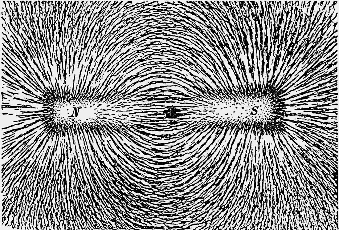
Read the visual model
Can attraction to a steel piece identify a magnet’s north pole?
Visual reasoning — after your attempt
No. Either pole can attract a suitable steel piece. Compare with a known marked magnet or another appropriate reference to identify the pole.
Compare two bar magnets using their marked ends. A steel piece may be attracted by either end because it responds to the field. Attraction to steel does not identify which pole faces it. Keep magnets away from items they could damage and avoid small powerful magnets.
Now read the green magnetic-field diagram. Outside a bar magnet the conventional direction is north to south; through the magnet it returns from south to north, forming closed loops. A compass has its own magnetized needle: the needle’s north-seeking end points along the local field. This direction convention is different from the electric positive-test-charge convention. North and south are magnetic pole names, not electric plus and minus signs.
The direction changes with position around the magnet, so a compass on one side need not point the same way as a compass elsewhere. The chosen field lines never cross in a simple field drawing because the field has one direction at a location. The iron-filings photograph shows a physical response and approximate pattern; the labeled diagram supplies directions and the closed-loop model that the photograph alone cannot show.
Cutting a magnet does not produce a lone north pole and a lone south pole. Each piece remains a magnet with both poles. This is an explanation model, not a suggested cutting activity. Attraction to ordinary steel is also different from comparing two marked magnetic poles: either end of a bar magnet can attract suitable steel.
Pause and explain
Can attraction to a steel piece identify a magnet’s north pole?
Check your reasoning after answering
No. Either pole can attract a suitable steel piece. Compare with a known marked magnet or another appropriate reference to identify the pole.
Part 4 · Make a fair distance investigation
Keep the objects, orientation, and measurement method comparable while changing separation. Record a measurable outcome such as force from supplied sensor data. Counting attracted items can be a useful rough comparison but also depends on arrangement and cannot give a universal force law.
Read the visual model
What must stay comparable when testing the effect of separation?
Visual reasoning — after your attempt
Use the same source, test object, orientation, and measuring method. Change separation deliberately and repeat observations to check variation.
A supplied data set may show weaker force at greater gaps. Conclude only for the tested pair and range. If orientation changes with distance, the investigation has changed two factors and cannot isolate separation as clearly.
In the supplied graph the independent variable is gap, measured in centimetres (cm). The vertical axis is force in millinewtons (mN): 1 mN is one thousandth of a newton. The three points are 12, 6 and 3 mN at 1, 2 and 3 cm. Read the trend and units before making a claim. The line segments help the eye connect records; they are not measurements between the points. These mN values are a separately labeled illustrative dataset; the initial evidence case used arbitrary response units rather than a calibrated force scale.
From 1 to 2 cm this particular supplied force halves, but that does not prove a universal distance rule for magnets. Magnet shape, orientation and the test object affect the relationship. The inverse-square rule for ideal isolated electric point charges is a different model; it must not be silently applied to bar magnets. Repeat each gap and record variation before drawing a stronger conclusion.
Pause and explain
What must stay comparable when testing the effect of separation?
Check your reasoning after answering
Use the same source, test object, orientation, and measuring method. Change separation deliberately and repeat observations to check variation.
Field strength and stored energy
The gap between interacting objects can affect force, while rearranging them can also change stored energy in the two-object system.
Current means the rate of electric-charge flow through a circuit, measured in amperes (A). A coil is wire wound into repeated turns. Together they make a useful cause-and-effect model: current through the turns produces a magnetic field, so the coil can act as an electromagnet. An iron core may strengthen its response. Increasing turns and increasing current are different changes and must be tested separately. The labeled schematic shows the idea; no homemade energized coil is needed.
A coil is wire arranged in turns. Current through a coil can produce a magnetic influence, making an electromagnet. Supplied coil records can test how turns, current and separation affect a response. A clip-lift count is a proxy, an indirect indicator, for performance and is not force in newtons. Do not infer a universal proportional rule from a short table or change coil turns and current together and call that an isolated comparison.
Potential energy belongs to the interacting arrangement, not a mysterious substance held by one object alone. Pushing repelling magnets closer can require work on the two-magnet system and increase its stored energy; releasing can transfer energy into motion and other paths. For an attractive pair, separating it can similarly require work and increase the store. Keep orientation and reference condition explicit before comparing arrangements.
Electric, magnetic and gravitational examples can all be modeled as forces acting across gaps with arrangement-dependent potential energy. A charged balloon and nearby hair illustrate electric interactions without creating new charge; charges are transferred or redistributed. A field model uses responses of a suitable test object to represent influence at different locations. It is not a line of material connecting the objects. A claim that effects require air can be tested against magnetic interaction across a vacuum, distinct from ordinary sound.
Follow the speaker cutaway: a fixed magnet provides a field, and current in a movable coil makes an interaction that can push the coil. The cone is attached to the coil. Changing current changes the force and lets the cone vibrate; the cone then makes the surrounding air vibrate. This is the chain that connects electric input, magnetic interaction, motion and sound. A diagram should explain the parts and connections, not merely label the word magnet.
For the additional illustrative turns investigation, current is held fixed and the trial clip counts are 3, 3, 4 for 10 turns; 5, 5, 6 for 20 turns; and 6, 7, 6 for 30 turns. Means are about 3.33, 5.33 and 6.33. Counts vary, so increased mean lifting performance does not prove exact proportionality or give force in newtons. These records test turns; the supplied evidence table separately tests current using matched turns.
Evidence to interpret
| Coil turns | Current (A) | Clip-lift count (illustrative) |
|---|---|---|
| 10 | 0.2 | 3 |
| 20 | 0.2 | 5 |
| 20 | 0.3 | 7 |
Use this method safely
Use supplied coil data; do not wind or energize homemade coils, use mains electricity or handle small powerful magnets. Any optional magnet observations use large classroom magnets with adult guidance.
Explain and apply
Use the coil records to ask an investigable question about each changed factor. Then draw a repelling-magnet energy model and contrast the work needed for separating an attractive pair.
- Isolate turns/current using the proper records.
- Distinguish proxy measurement from force.
- Model potential energy, orientation and work.
Reasoning and marking guidance — after your attempt
At fixed 0.2 A, changing turns from 10 to 20 raises the illustrative lift count 3→5; at fixed 20 turns, current 0.2→0.3 A changes it 5→7. These proxy outcomes support questions and a bounded trend, not a direct calibrated force law. Moving repelling magnets closer requires input work; separating attracting magnets can require input work instead. Energy is associated with the pair’s arrangement and can transfer into later motion.
Apply the whole unit · Interpret an interaction experiment
Illustrative measurements for the same magnet and test piece with fixed orientation: gaps 1, 2, and 3 cm give forces 0.8, 0.3, and 0.1 N. In a separate case, a charged rod attracts uncharged paper.
Your task
Graph the magnetic results, describe the supported trend, and explain why the data cannot establish a universal formula. Draw a charge-redistribution model for the paper without giving it an unsupported net charge.
What your response should show
- Use the supplied observations and measurements accurately; include units where needed.
- Explain the science behind your answer, rather than giving only a number or label.
- Show a labeled model, calculation, or evidence comparison as requested.
- State an assumption or limitation and suggest a useful next measurement.
Response guidance — after your attempt
The force decreases across the tested gaps, but three measurements for one setup do not establish a universal inverse-distance formula. Label axes and units and keep orientation fixed. In the paper, charges redistribute so the nearer region interacts more strongly; the total can remain neutral. Attraction alone is insufficient to claim opposite net charge.
Scientific references and adapted teaching resources
- OpenSciEd 8.1 Contact Forces — public unit overview
- OpenSciEd 8.3 Forces at a Distance — public unit overview
- OpenSciEd instructional model — storyline routines
- Creative Commons Attribution 4.0 — middle-school material license
- OpenSciEd 8.3 Lesson 3 — Framing Hypotheses (public handout)
- OpenStax: electric field direction and drawing conventions
- OpenStax: magnetic fields, closed loops and compass direction
Parent / teacher teaching notes
Keep electric charge signs and magnetic pole labels separate. Use the supplied measurements for quantitative work. Avoid small powerful magnets and any experiment involving wall electricity. Adaptation credit: OpenSciEd middle-school teaching routines and public task structures by OpenSciEd, CC BY 4.0. This independent version adds original explanatory text, data and figures, terminology support and a home-study schedule. It does not reproduce the complete teacher editions or their classroom validation. The illustrated study “Field strength and stored energy” is required curriculum content. Teach it before the associated application or distribute it over the assigned unit sessions; it is not an optional enrichment. Its practice/review/quiz response provides evidence of understanding. Model/data work must not be recorded as an actual physical experiment.
The key idea
Electric and magnetic forces can act through space; controlled tests reveal what changes their strength.
Worked examples
Example 1
- The same magnet, clip, and surface were used.
- The effect was observed at the shorter separation.
- Repeat the test to check reliability.
Example 2 · Worked application
- A neutral object has equal total positive and negative charges.
- The balloon's electric field can shift charge distribution slightly within the paper.
- The resulting polarization can produce net attraction without giving the paper a net charge.
Distinguish net charge from uneven distribution of charge.
Example 3
- The comb's field can slightly rearrange charges in the paper.
- Opposite charge closer to the comb can experience a stronger attraction than the farther like charge's repulsion.
Example 4 · Find and fix the mistake
- Test the claim against the stated conditions: Distinguish net charge from uneven distribution of charge.
- Certain materials can be magnetized by a nearby field without starting as permanent magnets; attraction alone is insufficient.
Distinguish net charge from uneven distribution of charge.
Example 5 · Field arrow versus force arrow
- Identify the field convention: it gives force direction for a positive test charge.
- A negative test charge responds in the opposite direction.
- Its force therefore points left, toward the positive source.
Changing the test-charge sign reverses force direction, not the defined field direction at that point.
Example 6 · Read a compass model
- Locate the compass on the outside field line.
- Follow the outside field direction from N to S.
- Above the middle in this symmetric drawing, the local tangent points right.
Do not label magnetic north as positive electric charge or assume every position has the same field direction.
Example 7 · Interpret the visual model
- Identify the represented objects, axes, labeled quantities and stated conditions before choosing a rule.
- A magnet can attract a suitable object before touching it. Compare the same objects at different distances. Do not assume every shiny metal is strongly attracted, because magnetic response depends on the material.
- It represents where and in what direction a source can influence suitable test objects. It does not show physical strings or prove identical force at every location.
Keep the model’s stated limits explicit: The blue arrows show electric-field direction, defined by the force on a small positive test charge. They point away from a positive source and toward a negative source. A negative test charge feels force opposite the field arrow. Lines represent a model at many positions, not strings or paths an object must follow. The drawing shows selected directions in a plane, not every field direction in three dimensions.
Avoid these mistakes
- A neutral object's attraction does not mean it had a net charge beforehand.
Check your understanding
A charged comb attracts small neutral paper pieces. Explain a model without assuming the paper gains a permanent charge.
Discuss the answer
Charge separation, or polarization, can produce a net attraction even while the paper remains neutral.
What happens to the poles when a bar magnet is cut into two pieces?
Discuss the answer
A field represents how an object could experience a force at a location without touching the source. Field diagrams use arrows to show direction and density of lines to suggest relative strength. The drawn lines are a model, not material strings filling space. Electric forces can attract or repel. Neutral objects can sometimes be attracted because their charges shift slightly within the material. Magnets have north and south poles, and ordinary cutting of a magnet makes two smaller magnets, each with both poles.
Return to the phenomenon
Illustrative tests use the same magnets and orientation with separations 1, 2 and 3 cm. Force magnitudes are 12, 6 and 3 arbitrary units. A paper barrier at 1 cm still gives 12 units. Identify evidence for an interaction across a gap, describe the distance trend and explain why the barrier does not prove a universal field law. Revise your first explanation using a named idea from the lesson. Mark the changed part and the evidence that supports it.
Compare explanations after your attempt
The objects affect one another without direct contact and remain coupled across the supplied paper barrier. The measured force decreases with separation in this range. These illustrative records do not establish a universal inverse-square rule for all magnet geometries or show that every barrier behaves like paper. A field is a model of the spatial influence, not a material stream of air.
What should we investigate next?
Which condition could be changed to test a remaining uncertainty in this explanation? State the predicted observation and what result would challenge your model.
Investigate, explain and revise
Use these tasks after the three teaching sessions as needed. Discuss an attempted explanation before opening response guidance; a matching sentence is less important than a supported mechanism.
Activity 1 · Explain the new evidence case
Use the visible scenario above, Parts 1–4 and your first notebook model. No outside reading or equipment is required.
Your task
Illustrative tests use the same magnets and orientation with separations 1, 2 and 3 cm. Force magnitudes are 12, 6 and 3 arbitrary units. A paper barrier at 1 cm still gives 12 units. Identify evidence for an interaction across a gap, describe the distance trend and explain why the barrier does not prove a universal field law. Write 100–150 words or give a labeled drawing with an equivalent oral explanation.
Success criteria
- Use two relevant stated records or conditions.
- Explain the mechanism rather than only repeat a definition.
- Label observation and inference.
- Name a changed model feature or a remaining uncertainty.
Hint
Read the stated boundary and conditions before selecting a relationship. The unit’s worked examples show intermediate steps.
Response guidance — discuss after your attempt
The objects affect one another without direct contact and remain coupled across the supplied paper barrier. The measured force decreases with separation in this range. These illustrative records do not establish a universal inverse-square rule for all magnet geometries or show that every barrier behaves like paper. A field is a model of the spatial influence, not a material stream of air.
Activity 2 · Read and extend the figure
Study the new labeled figure and its caption, then compare it with the associated teaching part.
Your task
Why not change the test magnet size between positions? Explain what each important label represents. Add one missing feature that would be needed for a different question, and explain why the original figure leaves it out.
Success criteria
- Answer the figure question with its stated labels.
- Connect the visual representation to the scientific idea.
- Identify a specific limitation from the caption.
- Propose a useful change without misrepresenting supplied evidence.
Hint
The three positions stand for separate tests with the same test object and orientation. The force magnitudes are illustrative and show decreasing strength over this tested range, not a universal formula. A mapped field describes how a suitable test object responds at different locations.
Response guidance — discuss after your attempt
That would change another cause of force, confounding the intended distance comparison. The three positions stand for separate tests with the same test object and orientation. The force magnitudes are illustrative and show decreasing strength over this tested range, not a universal formula. A mapped field describes how a suitable test object responds at different locations.
Words to know
- field
- A model describing the influence an object has in the space around it.
- repel
- Push apart.
- controlled variable
- A factor kept the same during a comparison.
- model
- A representation that explains selected features and makes predictions; it leaves other details out.
- evidence
- Relevant observations or records used to support or challenge a claim.
- system boundary
- The chosen limit separating the objects being studied from their surroundings.
- assumption
- A condition taken as true for a model or calculation and needing to be checked against the case.
- electric charge
- A property responsible for electric interactions. In this introductory model, excess electrons give an object net negative charge and an electron deficit can give it net positive charge.
- polarization
- A slight shift or separation of positive and negative charge within material; the whole object can remain electrically neutral.
- current
- The rate of electric-charge flow through a chosen part of a circuit, measured in amperes (A).
- coil
- Wire wound into repeated turns. Current through the turns produces a magnetic field.
- electromagnet
- A magnet produced by electric current, often using a wire coil and an iron core.
- compass
- An instrument with a magnetized needle; its north-seeking end points along the local magnetic field.
In the real world
Exit check
Why not change the test magnet size between positions? Explain the relevant mechanism and one model limitation.
Check your explanation after answering
That would change another cause of force, confounding the intended distance comparison. The three positions stand for separate tests with the same test object and orientation. The force magnitudes are illustrative and show decreasing strength over this tested range, not a universal formula. A mapped field describes how a suitable test object responds at different locations.
Explain your reasoning without notes. If a key idea is missing, revisit the lesson and try again.
Pressure & Buoyant Forces
Learning goals
- I can describe fluid pressure and how contact area affects pressure.
- I can explain floating using upward buoyant force and downward weight.
Readings for this unit
Before this unit
Divide force by area and distinguish a solid from a fluid.
Use three teaching sessions of about 40–45 minutes: first observe the phenomenon, draft a model and study Parts 1–2; next explain Parts 3–4 with the figures and evidence; then work the application, examples, practice, model revision and exit check. Divide any difficult part into smaller steps and revisit after feedback. Investigations, review and quizzes have separate sessions. Study the four visual parts across the scheduled sessions, then use the illustrated worked case and independent transfer questions. Extend or revisit a session when the learner cannot explain the figure; completion time is a proposed allocation, not a mastery guarantee.
Start with something to explain
What would explain the observations in pressure & buoyant forces?
Illustrative evidence case. Illustrative pistons share fluid pressure 2,000 Pa. Areas are 0.01 and 0.04 m². A floating object separately displaces water with weight 8 N.
Notice and wonder
Which displacement must be smaller in the ideal lift? Write two observations from the supplied record without guessing their cause. Include a quantity and its unit when given. An observation is what was recorded; an inference is what you think explains it.
Write one question about why the pattern occurs and one question about a comparison that could distinguish competing explanations. A testable question identifies what could be observed or measured.
Your first model
Before reading the model answer, sketch the named objects or particles and label what you think changes. Calculate piston forces and explain why a force gain is not free energy. Identify the upward force in the floating model. Keep this first version so you can compare it with your later explanation.
Build the language from the idea
- pressure
- Force acting per unit area.
- fluid
- A liquid or gas that flows.
- buoyant force
- The net upward force a fluid exerts on an immersed object.
- model
- A representation that explains selected features and makes predictions; it leaves other details out.
- evidence
- Relevant observations or records used to support or challenge a claim.
- system boundary
- The chosen limit separating the objects being studied from their surroundings.
- assumption
- A condition taken as true for a model or calculation and needing to be checked against the case.
Liquids and gases are fluids: they flow and push on surfaces. Pressure is force per unit area. If the same force acts on a smaller area, pressure is greater. That is why snowshoes can reduce how far a person sinks into snow: they spread weight over more area.
Within a stationary liquid, pressure increases with depth because more fluid lies above. Fluid pushes in all directions. The greater pressure on the lower parts of a submerged object produces a net upward force called buoyancy. This is different from the object’s weight, which acts downward.
An object floating steadily has equal upward buoyant force and downward weight. Zero net force does not mean that no forces act. When an object sinks, the forces may initially be unbalanced downward; fluid resistance also matters once it moves. Changing the shape of a sealed boat hull can increase the volume of water displaced without greatly increasing mass.
Pressure is force spread over an area. For the same force, a smaller area produces greater pressure. Within a resting liquid, pressure generally increases with depth because more liquid above contributes weight.
A fluid pushes on an immersed object from all sides. The greater pressure at the bottom than at the top creates a net upward buoyant force. In an introductory model, that force equals the weight of fluid displaced by the submerged part.
A floating object reaches a balance between its weight and buoyant force. A heavier load makes a boat sit deeper, displacing more water. If water enters the boat, its average density may rise and the available buoyancy may no longer support it. Keep depth, volume and density separate in the explanation.
Build your understanding
Where this fits
This unit helps answer the chapter question: How can forces explain stability and changes in motion? Keep a notebook table with the question, evidence, explanation and one unresolved issue. Revise a previous model only when you can name the new evidence or idea that changes it.
Use three teaching sessions of about 40–45 minutes: first observe the phenomenon, draft a model and study Parts 1–2; next explain Parts 3–4 with the figures and evidence; then work the application, examples, practice, model revision and exit check. Divide any difficult part into smaller steps and revisit after feedback. Investigations, review and quizzes have separate sessions.
Part 1 · Relate force to contact area
Pressure is force distributed over area. For the simple uniform-pressure model, pressure=force/area. The same force concentrated on a smaller area gives larger pressure. Use consistent area units; a square centimeter and a square meter are not interchangeable. Pressure is not the same quantity as total force.
Read the visual model
Trace the equal red force arrows first. Then compare the labeled areas. The wider side has twice the contact area, so each square metre receives half as much force. Side-view width alone is not area; the labels provide the needed measurement.
If the broad contact area is doubled again to 0.04 m² while the force stays 20 N, what pressure follows?
Visual reasoning — after your attempt
P = 20/0.04 = 500 Pa. Pressure falls because the force is spread farther; the total force remains 20 N.
A 20 N force over 0.01 m² produces 2000 Pa, since 1 Pa=1 N/m². Over 0.02 m² it produces 1000 Pa. Spreading the same load changes pressure without changing its total downward force.
A pascal, abbreviated Pa, is a pressure unit: 1 Pa = 1 N/m². Newtons describe force; square metres describe contact area. Pressure combines them. A thumb and an open palm can push with the same force, yet concentrate that force over different areas. The symbol P means pressure, F means the perpendicular force on a surface, and A means its area; P = F/A is a uniform-contact or average-pressure model.
Snowshoes spread a person’s downward load over more snow, reducing the average pressure and often reducing how far the person sinks into it. They do not reduce the person’s mass or gravitational weight. Real snow deforms, and pressure need not be exactly uniform, so the model explains the comparison rather than predicting a precise sinking depth.
Pause and explain
Why do broad snowshoes reduce average pressure on snow?
Check your reasoning after answering
They spread a similar weight over a larger area. Dividing the force by a larger area gives a smaller average pressure.
Part 2 · Explain pressure within a fluid
A fluid exerts forces on surfaces it contacts. In a stationary liquid under gravity, pressure generally increases with depth because more overlying fluid must be supported. Pressure at the same depth is not determined simply by how wide the container looks. Air pressure also exerts forces even though air is invisible.
Read the visual model
The graph and tank show the same two selected depths. Longer side-force arrows correspond to larger pressure on equal-size surface patches. The zero on the graph is a zero increase above air pressure, not an absence of air molecules or total pressure.
What pressure increase does the model predict at 1.5 m, and would a wider tank at the same depth change that value?
Visual reasoning — after your attempt
15 kPa above the common surface air pressure. Tank width alone does not change it in this stationary, uniform-density, open-water model.
Compare two points at different depths in the same open water container. The lower point has greater pressure. State liquid density and surface pressure when comparing different containers rather than using depth as the only condition.
Depth here means vertical distance below the free water surface. Water lower down must support more overlying fluid, so its pressure is greater. Two connected points at the same depth in the same stationary water have equal pressure even when the container has different widths. The comparison assumes the same density, the same pressure at the surface and water at rest.
To read the graph, choose a depth on the horizontal axis and move up to the blue line. At 1 m the increase above surface air pressure is 10 kPa. The prefix kilo means one thousand: 10 kPa = 10,000 Pa. At 2 m the increase is 20 kPa. The surface does not have zero total pressure: air already presses on it. The graph subtracts that common air-pressure reference so the change caused by water is easier to see.
An optional quantitative model is ΔP = ρgh. Read ΔP as the pressure increase, ρ (rho) as fluid density in kg/m³, g as gravitational force per kilogram in N/kg, and h as depth in metres. Here ρ = 1,000 and g = 10, giving ΔP = 10,000h Pa. You can use the graph without memorizing this formula. A denser liquid would give a steeper pressure-versus-depth line under the same conditions.
Pressure is not a downward arrow. Fluid at a point can push on a small surface facing any direction; the force is perpendicular to that surface. Water therefore pushes down on the top of an immersed object, up on its bottom, and inward on its sides. To explain buoyancy, compare all those water forces rather than treating water as a hand pushing only from underneath.
Pause and explain
At equal depths in the same stationary liquid, does a wider container necessarily give greater pressure?
Check your reasoning after answering
No. With the same surface pressure and liquid density, pressure at a given depth does not depend simply on container width.
Part 3 · Connect displaced fluid to buoyant force
Fluid pressure on a submerged object varies with depth, often producing a net upward buoyant force. Its magnitude equals the weight of displaced fluid in the introductory model. An object floating steadily displaces fluid whose weight balances its own weight. This force acts even on an object that sinks.
Read the visual model
Follow the cylinder scale before calculating. Subtract the initial reading from the final reading, convert volume units if necessary, find the mass of that volume of water, then find its weight. This sequence explains where the buoyancy value comes from.
If another fully immersed block raises the water from 400 to 700 mL under the same conditions, what buoyant force does it receive? Can that result alone tell you whether it sinks?
Visual reasoning — after your attempt
The displaced volume is 300 mL, so water mass is 0.30 kg and buoyancy is 3 N. You also need the object’s weight and any other forces to decide its motion.
A submerged object can have an upward buoyant force smaller than its downward weight, so it accelerates downward. Floating does not mean gravity disappeared, and sinking does not mean the fluid provides no support at all.
Now connect the pressure model to a complete water-force diagram. The block’s bottom is deeper than its top, so the upward water force on the bottom is greater than the downward water force on the top. At corresponding depths the horizontal side forces oppose and cancel. In the illustrated rectangular-block model, 5 N upward minus 2 N downward leaves 3 N upward. This resultant, or combined net water force, is the buoyant force.
Do not draw buoyancy as an extra force alongside all of the individual pressure forces and add everything together. The single buoyancy arrow is a convenient replacement for their net effect. You can use either the individual water-force model or its one-arrow summary. Weight is another interaction: Earth pulls the object downward. It belongs on the complete object force diagram, but it was intentionally left out of the water-only comparison.
Displaced water is water excluded from the space occupied by an object’s immersed portion. When a fully immersed block raises a cylinder reading from 400 to 650 mL, the displaced volume is 250 mL. It is not 650 mL, and it is not automatically the block’s mass. With water density 1 g/mL, that volume of water would have mass 250 g = 0.25 kg. Its weight is 0.25 × 10 = 2.5 N in our rounded model.
Archimedes’ principle states that buoyancy equals the weight of the displaced fluid. It is another way to describe the net pressure-force result. In symbols, Fᵦ = ρVg: Fᵦ means buoyant force, ρ is the fluid’s density, V is the immersed volume, and g is gravitational strength. The object’s own density is not the density to insert here. If the same immersed volume displaces a denser fluid, the buoyant force is larger.
Check this against the pressure-force model: face area 0.01 m² × height 0.03 m = immersed volume 0.0003 m³. That much water has mass 1,000 × 0.0003 = 0.30 kg and weight 3 N. This matches 5 N − 2 N. We have explained one result using two connected representations, rather than presenting two unrelated formulas.
A floating hull often has only part of its total volume beneath the surface. Count that submerged external volume, including any dry enclosed interior that excludes water, rather than the hull’s full above-and-below-water volume. A sinking object also displaces water and receives buoyancy. Sinking means the other forces do not balance it; it does not mean the water stops exerting an upward force.
Pause and explain
Does an object that sinks have zero buoyant force?
Check your reasoning after answering
No. It still experiences upward buoyancy. If its weight exceeds that force and other forces are neglected, the net force is downward.
Part 4 · Distinguish floating from suspended or supported
A floating object reaches force balance while partly or fully immersed. A fully immersed object can be neutrally buoyant if buoyancy equals weight. A tether or floor can supply extra forces, so being motionless underwater does not alone establish neutral buoyancy. Always draw all interactions.
Read the visual model
Read each waterline and identify external support before comparing arrows. All arrows in the three-case figure use the same force scale. The middle block receives an upward force even though its net force is downward.
Could an underwater block be motionless with buoyancy smaller than weight? Give a complete force balance.
Visual reasoning — after your attempt
Yes. For example, buoyancy 2 N up plus a string force 2 N up balances weight 4 N down. If resting on the floor, the floor could supply the extra upward support instead.
If weight is 12 N and buoyancy is 8 N, a supporting string could provide the remaining 4 N upward. The object is stationary due to three forces, not because its average density equals the fluid density.
Start each force comparison by naming the object being studied. In the three diagrams it is the block, not the water plus block together. Weight is the downward force Earth exerts on that object. Buoyancy is the water’s net force on it. A string, hand or container floor can exert another force; include it whenever present. Choose upward as positive and combine upward contributions before subtracting downward ones.
For the floating block, 3 N buoyancy − 3 N weight = 0 N. For the heavy block just released from rest, 2 N buoyancy − 4 N weight = −2 N, meaning 2 N downward. The held block has 2 N buoyancy + 2 N string tension − 4 N weight = 0 N. Tension means the pulling force transmitted by the taut string. These balances explain why “it stays still” is insufficient evidence for equal buoyancy and weight unless you have ruled out other support.
A zero net force predicts zero acceleration; it does not always predict zero speed. These stationary examples are at rest by construction. A real block sinking later can move at constant downward speed when upward water drag plus buoyancy balance its weight. Drag is the fluid’s resistance to relative motion. Near the moment of release from rest, we omit drag to make the initial force comparison clear.
Shape can matter because it changes how much water an object can exclude before becoming fully immersed or flooded. The same clay can be shaped into a solid lump or a hollow hull. The lump in the example displaces at most 150 cm³, insufficient to balance its 3 N weight in water. The hull can float if it excludes 300 cm³ before the rim dips underwater. This is a capacity and stability condition, not a guarantee that any hollow shape will float.
As weight is added to a floating hull, it usually sits deeper and displaces more water. It can balance a larger load only while sufficient displacement is possible without flooding, tipping or structural failure. If water enters the hull, that extra water can add weight and reduce the dry space excluding water. This is why a leak can change the force balance even though the hull’s material remains the same.
Pause and explain
What extra information is needed for a motionless underwater object?
Check your reasoning after answering
Determine whether a string, floor, or other contact supplies a force. Rest alone does not establish that buoyancy and weight balance each other.
Apply the whole unit · Explain two pressure and buoyancy cases
Illustrative case: a 40 N load rests on area 0.02 m². A separate submerged object has weight 12 N and displaces fluid weighing 8 N. Ignore drag at the initial instant.
Your task
Calculate average pressure, draw the submerged object’s forces, predict its initial acceleration direction if released, and calculate the string force needed to hold it still. Explain one limitation of each model.
What your response should show
- Use the supplied observations and measurements accurately; include units where needed.
- Explain the science behind your answer, rather than giving only a number or label.
- Show a labeled model, calculation, or evidence comparison as requested.
- State an assumption or limitation and suggest a useful next measurement.
Response guidance — after your attempt
Pressure is 40/0.02=2000 Pa under the uniform average model. Buoyancy is 8 N upward and weight 12 N downward, so the released object initially has net force 4 N downward. A 4 N upward string force balances it. Actual pressure can vary over contact, and fluid motion or drag can alter later motion.
Scientific references and adapted teaching resources
- OpenSciEd 8.1 Contact Forces — public unit overview
- OpenSciEd 8.3 Forces at a Distance — public unit overview
- OpenSciEd instructional model — storyline routines
- Creative Commons Attribution 4.0 — middle-school material license
Parent / teacher teaching notes
Use force arrows before calculating differences. Connect this unit to average density but keep pressure, force, and mass separate. Use supplied data rather than improvised pressurized apparatus. Adaptation credit: OpenSciEd middle-school teaching routines and public task structures by OpenSciEd, CC BY 4.0. This independent version adds original explanatory text, data and figures, terminology support and a home-study schedule. It does not reproduce the complete teacher editions or their classroom validation. Have the learner trace depth → pressure difference → net water force → displaced-water weight before calculating floating or sinking. Assign the changed cylinder-reading exercise and ask them to explain which mass belongs in each calculation.
The key idea
Fluids exert pressure. A steadily floating object has balanced buoyant force and weight.
Worked examples
Example 1
- Steady floating means no vertical acceleration.
- The vertical forces balance.
Example 2 · Worked application
- Displaced water mass=1000×0.003=3 kg.
- Its weight is 3×10=30 N.
- Buoyant force equals the weight of displaced fluid in this model.
Use displaced fluid volume, not the container's total water volume.
Example 3
- Pressure=force/area=200/0.5=400 Pa.
- Halving area gives 200/0.25=800 Pa.
Example 4 · Find and fix the mistake
- Test the claim against the stated conditions: Use displaced fluid volume, not the container's total water volume.
- Gravity still acts. At floating equilibrium, upward buoyancy balances downward weight.
Use displaced fluid volume, not the container's total water volume.
Example 5 · From pressure differences to buoyancy
- Compare water forces on the top and bottom: 5 N upward − 2 N downward = 3 N upward. The horizontal side forces cancel.
- Find immersed volume from face area and height: 0.01 m² × 0.03 m = 0.0003 m³.
- That volume of water has mass 1,000 kg/m³ × 0.0003 m³ = 0.30 kg. Its weight is 0.30 kg × 10 N/kg = 3 N.
- Both methods describe the same net water force. Use its buoyancy arrow instead of, not in addition to, the individual pressure arrows. To predict the object’s motion, compare buoyancy with weight and any other forces.
The graph uses pressure above a uniform air-pressure reference. That uniform reference cancels over the closed block surface, so the net-force result is unchanged.
Avoid these mistakes
- Buoyant force exists on sinking objects as well as floating objects.
Check your understanding
A 200 N force is spread over 0.5 m². Find pressure and compare with the same force on 0.25 m².
Discuss the answer
400 Pa initially; reducing the area by half doubles pressure to 800 Pa.
Why does a loaded floating boat sit lower in the water?
Discuss the answer
Pressure is force spread over an area. For the same force, a smaller area produces greater pressure. Within a resting liquid, pressure generally increases with depth because more liquid above contributes weight. A fluid pushes on an immersed object from all sides. The greater pressure at the bottom than at the top creates a net upward buoyant force. In an introductory model, that force equals the weight of fluid displaced by the submerged part.
Return to the phenomenon
Illustrative pistons share fluid pressure 2,000 Pa. Areas are 0.01 and 0.04 m². A floating object separately displaces water with weight 8 N. Calculate piston forces and explain why a force gain is not free energy. Identify the upward force in the floating model. Revise your first explanation using a named idea from the lesson. Mark the changed part and the evidence that supports it.
Compare explanations after your attempt
Using force = pressure × area, the piston forces are 20 N and 80 N. In an ideal hydraulic arrangement, the larger force acts through a smaller distance while displaced volumes balance, so energy is not created. The displaced-fluid model gives an 8 N buoyant force; floating equilibrium also requires the object’s weight to be balanced.
What should we investigate next?
Which condition could be changed to test a remaining uncertainty in this explanation? State the predicted observation and what result would challenge your model.
Investigate, explain and revise
Use these tasks after the three teaching sessions as needed. Discuss an attempted explanation before opening response guidance; a matching sentence is less important than a supported mechanism.
Activity 1 · Explain the new evidence case
Use the visible scenario above, Parts 1–4 and your first notebook model. No outside reading or equipment is required.
Your task
Illustrative pistons share fluid pressure 2,000 Pa. Areas are 0.01 and 0.04 m². A floating object separately displaces water with weight 8 N. Calculate piston forces and explain why a force gain is not free energy. Identify the upward force in the floating model. Write 100–150 words or give a labeled drawing with an equivalent oral explanation.
Success criteria
- Use two relevant stated records or conditions.
- Explain the mechanism rather than only repeat a definition.
- Label observation and inference.
- Name a changed model feature or a remaining uncertainty.
Hint
Read the stated boundary and conditions before selecting a relationship. The unit’s worked examples show intermediate steps.
Response guidance — discuss after your attempt
Using force = pressure × area, the piston forces are 20 N and 80 N. In an ideal hydraulic arrangement, the larger force acts through a smaller distance while displaced volumes balance, so energy is not created. The displaced-fluid model gives an 8 N buoyant force; floating equilibrium also requires the object’s weight to be balanced.
Activity 2 · Read and extend the figure
Study the new labeled figure and its caption, then compare it with the associated teaching part.
Your task
Which displacement must be smaller in the ideal lift? Explain what each important label represents. Add one missing feature that would be needed for a different question, and explain why the original figure leaves it out.
Success criteria
- Answer the figure question with its stated labels.
- Connect the visual representation to the scientific idea.
- Identify a specific limitation from the caption.
- Propose a useful change without misrepresenting supplied evidence.
Hint
The supplied ideal fluid pressure produces force equal to pressure times area. A larger output force does not create energy: balanced displaced volume gives a smaller output displacement. The boxes are not a scale construction drawing and omit losses, seals and actual pressure variations.
Response guidance — discuss after your attempt
The larger-area output piston moves a shorter distance when displaced fluid volumes match. The supplied ideal fluid pressure produces force equal to pressure times area. A larger output force does not create energy: balanced displaced volume gives a smaller output displacement. The boxes are not a scale construction drawing and omit losses, seals and actual pressure variations.
Words to know
- pressure
- Force acting per unit area.
- fluid
- A liquid or gas that flows.
- buoyant force
- The net upward force a fluid exerts on an immersed object.
- model
- A representation that explains selected features and makes predictions; it leaves other details out.
- evidence
- Relevant observations or records used to support or challenge a claim.
- system boundary
- The chosen limit separating the objects being studied from their surroundings.
- assumption
- A condition taken as true for a model or calculation and needing to be checked against the case.
In the real world
Exit check
Which displacement must be smaller in the ideal lift? Explain the relevant mechanism and one model limitation.
Check your explanation after answering
The larger-area output piston moves a shorter distance when displaced fluid volumes match. The supplied ideal fluid pressure produces force equal to pressure times area. A larger output force does not create energy: balanced displaced volume gives a smaller output displacement. The boxes are not a scale construction drawing and omit losses, seals and actual pressure variations.
Explain your reasoning without notes. If a key idea is missing, revisit the lesson and try again.
Problem 1
Answer and explanation
Yes. With zero net force its velocity does not change. It can remain at rest or continue moving at constant speed in a straight line.
Yes. With zero net force its velocity does not change. It can remain at rest or continue moving at constant speed in a straight line.
Response criteria
- Use the supplied conditions and relevant evidence.
- Explain the scientific mechanism or calculation.
- State a meaningful limitation or testable next step.
Problem 2
Answer and explanation
Yes, at constant velocity in the stated simple model. Zero net force does not require zero velocity.
Yes, at constant velocity in the stated simple model. Zero net force does not require zero velocity.
Response criteria
- Use the supplied conditions and relevant evidence.
- Explain the scientific mechanism or calculation.
- State a meaningful limitation or testable next step.
Problem 3
Answer and explanation
Net 9 N right; acceleration 9/3 = 3 m/s² right. Its initial leftward motion slows because acceleration opposes velocity.
Subtract opposing forces on the same receiver.
Compare acceleration direction with the supplied velocity.
Net 9 N right; acceleration 9/3 = 3 m/s² right. Its initial leftward motion slows because acceleration opposes velocity.
Response criteria
- Use the named labels, directions or supplied quantities accurately.
- Connect the visual evidence to the scientific mechanism or calculation.
- State the relevant model conditions or limitation.
Problem 4
Answer and explanation
Only one acts on the cart. Adding a force on the person to the forces on the cart mixes receivers and gives an invalid net force.
Only one acts on the cart. Adding a force on the person to the forces on the cart mixes receivers and gives an invalid net force.
Response criteria
- Use the supplied conditions and relevant evidence.
- Explain the scientific mechanism or calculation.
- State a meaningful limitation or testable next step.
Problem 5
Answer and explanation
8−3=5 N rightward. The cart-on-hand partner remains 8 N leftward; it is not the cart’s net force.
8−3=5 N rightward. The cart-on-hand partner remains 8 N leftward; it is not the cart’s net force.
Response criteria
- Use the supplied conditions and relevant evidence.
- Explain the scientific mechanism or calculation.
- State a meaningful limitation or testable next step.
Problem 6
Answer and explanation
Required net is 4×1.5 = 6 N right, leaving 4 N resistance left. The cart-on-hand partner belongs on the hand’s diagram, not the cart’s.
Use measured acceleration to find net force.
Keep the third-law partner on its separate receiver.
Required net is 4×1.5 = 6 N right, leaving 4 N resistance left. The cart-on-hand partner belongs on the hand’s diagram, not the cart’s.
Response criteria
- Use the named labels, directions or supplied quantities accurately.
- Connect the visual evidence to the scientific mechanism or calculation.
- State the relevant model conditions or limitation.
Problem 7
Answer and explanation
Greater mass also means greater resistance to acceleration. Since gravitational force is mg, force divided by mass gives g for each object when drag is neglected.
Greater mass also means greater resistance to acceleration. Since gravitational force is mg, force divided by mass gives g for each object when drag is neglected.
Response criteria
- Use the supplied conditions and relevant evidence.
- Explain the scientific mechanism or calculation.
- State a meaningful limitation or testable next step.
Problem 8
Answer and explanation
Moving locations changes the gravitational field and weight, not the stated amount of matter.
Moving locations changes the gravitational field and weight, not the stated amount of matter.
Response criteria
- Use the supplied conditions and relevant evidence.
- Explain the scientific mechanism or calculation.
- State a meaningful limitation or testable next step.
Problem 9
Hints
Use the illustrated study titled Gravity: masses, distance and free fall. Keep the observations, model and conditions separate.
Answer and explanation
The force rises from 8 to 16 relative units when one mass doubles at fixed separation, and falls to 2 when separation doubles at the reference masses. These model comparisons support attractive, mass- and distance-dependent interaction under the stated conditions. Feather/stone differences in air also involve drag and inertia; an ideal negligible-drag comparison does not depend on mass in the same way. Separate receivers for the interaction pair and name the model limit.
The force rises from 8 to 16 relative units when one mass doubles at fixed separation, and falls to 2 when separation doubles at the reference masses. These model comparisons support attractive, mass- and distance-dependent interaction under the stated conditions. Feather/stone differences in air also involve drag and inertia; an ideal negligible-drag comparison does not depend on mass in the same way. Separate receivers for the interaction pair and name the model limit.
Response criteria
- Compare one changed factor at a time.
- Explain attraction and appropriate force receivers.
- Distinguish gravity-only motion from significant drag.
Problem 10
Answer and explanation
Horizontal velocity 6 m/s; vertical velocity 0; vertical acceleration −10 m/s². Gravity continues acting downward.
Separate the two velocity components.
Distinguish zero vertical velocity from zero acceleration.
Response criteria
- State all three values with units.
- Keep gravity downward.
- Avoid claiming zero total velocity.
Problem 11
Answer and explanation
At the top after 0.8 s: horizontal velocity 3 m/s, vertical velocity 0, vertical acceleration −10 m/s². Total flight is 1.6 s, so range is 4.8 m under the same-height ideal model.
Vertical velocity loses 10 m/s each second, reaching zero after 0.8 s.
Symmetric ideal same-height return takes twice that time; multiply by horizontal speed.
At the top after 0.8 s: horizontal velocity 3 m/s, vertical velocity 0, vertical acceleration −10 m/s². Total flight is 1.6 s, so range is 4.8 m under the same-height ideal model.
Response criteria
- Use the named labels, directions or supplied quantities accurately.
- Connect the visual evidence to the scientific mechanism or calculation.
- State the relevant model conditions or limitation.
Problem 12
Answer and explanation
No. A charged object can attract a neutral object through polarization. Repulsion in a suitable simple test can be stronger evidence of like net charges.
No. A charged object can attract a neutral object through polarization. Repulsion in a suitable simple test can be stronger evidence of like net charges.
Response criteria
- Use the supplied conditions and relevant evidence.
- Explain the scientific mechanism or calculation.
- State a meaningful limitation or testable next step.
Problem 13
Answer and explanation
That would change another cause of force, confounding the intended distance comparison.
That would change another cause of force, confounding the intended distance comparison.
Response criteria
- Use the supplied conditions and relevant evidence.
- Explain the scientific mechanism or calculation.
- State a meaningful limitation or testable next step.
Problem 14
Hints
Use the illustrated study titled Field strength and stored energy. Keep the observations, model and conditions separate.
Answer and explanation
At fixed 0.2 A, changing turns from 10 to 20 raises the illustrative lift count 3→5; at fixed 20 turns, current 0.2→0.3 A changes it 5→7. These proxy outcomes support questions and a bounded trend, not a direct calibrated force law. Moving repelling magnets closer requires input work; separating attracting magnets can require input work instead. Energy is associated with the pair’s arrangement and can transfer into later motion.
At fixed 0.2 A, changing turns from 10 to 20 raises the illustrative lift count 3→5; at fixed 20 turns, current 0.2→0.3 A changes it 5→7. These proxy outcomes support questions and a bounded trend, not a direct calibrated force law. Moving repelling magnets closer requires input work; separating attracting magnets can require input work instead. Energy is associated with the pair’s arrangement and can transfer into later motion.
Response criteria
- Isolate turns/current using the proper records.
- Distinguish proxy measurement from force.
- Model potential energy, orientation and work.
Problem 15
Answer and explanation
Positive: upward. Negative: downward. Field direction uses the positive-test-charge convention.
Identify the definition of electric-field direction.
Reverse the force direction for a negative test charge.
Response criteria
- Name both directions.
- Explain the sign convention.
- Distinguish field from a path.
Problem 16
Answer and explanation
Outside N to S; inside S to N. Each cut piece has both N and S poles.
Trace a complete loop.
Identify both poles on each smaller magnet.
Response criteria
- Give both directions.
- Keep both poles on each piece.
- Distinguish magnetic poles from electric charge.
Problem 17
Answer and explanation
The negative charge feels force right, opposite the positive-test-charge convention. A neutral paper piece can polarize while keeping balanced total positive and negative charge.
Use the field convention before choosing the test-charge force.
Distinguish charge redistribution from transfer that changes net charge.
The negative charge feels force right, opposite the positive-test-charge convention. A neutral paper piece can polarize while keeping balanced total positive and negative charge.
Response criteria
- Use the named labels, directions or supplied quantities accurately.
- Connect the visual evidence to the scientific mechanism or calculation.
- State the relevant model conditions or limitation.
Problem 18
Answer and explanation
No. With the same surface pressure and liquid density, pressure at a given depth does not depend simply on container width.
No. With the same surface pressure and liquid density, pressure at a given depth does not depend simply on container width.
Response criteria
- Use the supplied conditions and relevant evidence.
- Explain the scientific mechanism or calculation.
- State a meaningful limitation or testable next step.
Problem 19
Answer and explanation
The larger-area output piston moves a shorter distance when displaced fluid volumes match.
The larger-area output piston moves a shorter distance when displaced fluid volumes match.
Response criteria
- Use the supplied conditions and relevant evidence.
- Explain the scientific mechanism or calculation.
- State a meaningful limitation or testable next step.
Problem 20
Answer and explanation
The string supplies 3 N upward. Buoyancy alone is smaller than weight; the third force is needed to make the held object’s net force zero.
List all forces on the object.
Use 6+T−9 = 0 without calling the held state unsupported floating.
The string supplies 3 N upward. Buoyancy alone is smaller than weight; the third force is needed to make the held object’s net force zero.
Response criteria
- Use the named labels, directions or supplied quantities accurately.
- Connect the visual evidence to the scientific mechanism or calculation.
- State the relevant model conditions or limitation.