Electric & Magnetic Forces · Grade 8 Science
Chapter: ForcesElectric & Magnetic Forces
Learning goals
- I can use a field model to describe forces between objects that are not touching.
- I can design a fair test of how magnet separation affects its interaction with another object.
- I can interpret coil-strength records and model stored energy in changed field arrangements.
Readings for this unit
Before this unit
Know like and unlike charges and magnetic poles.
Use three teaching sessions of about 40–45 minutes: first observe the phenomenon, draft a model and study Parts 1–2; next explain Parts 3–4 with the figures and evidence; then work the application, examples, practice, model revision and exit check. Divide any difficult part into smaller steps and revisit after feedback. Investigations, review and quizzes have separate sessions. Study the four visual parts across the scheduled sessions, then use the illustrated worked case and independent transfer questions. Extend or revisit a session when the learner cannot explain the figure; completion time is a proposed allocation, not a mastery guarantee.
Start with something to explain
What would explain the observations in electric & magnetic forces?
Illustrative evidence case. Illustrative tests use the same magnets and orientation with separations 1, 2 and 3 cm. Force magnitudes are 12, 6 and 3 arbitrary units. A paper barrier at 1 cm still gives 12 units. Compare the force arrows in the three cases. What changes when only one charge sign changes, and which object receives each force?
Notice and wonder
Why not change the test magnet size between positions? Write two observations from the supplied record without guessing their cause. Include a quantity and its unit when given. An observation is what was recorded; an inference is what you think explains it.
Write one question about why the pattern occurs and one question about a comparison that could distinguish competing explanations. A testable question identifies what could be observed or measured.
Your first model
Before reading the model answer, sketch the named objects or particles and label what you think changes. Identify evidence for an interaction across a gap, describe the distance trend and explain why the barrier does not prove a universal field law. Keep this first version so you can compare it with your later explanation.
Build the language from the idea
- field
- A model describing the influence an object has in the space around it.
- repel
- Push apart.
- controlled variable
- A factor kept the same during a comparison.
- model
- A representation that explains selected features and makes predictions; it leaves other details out.
- evidence
- Relevant observations or records used to support or challenge a claim.
- system boundary
- The chosen limit separating the objects being studied from their surroundings.
- assumption
- A condition taken as true for a model or calculation and needing to be checked against the case.
- electric charge
- A property responsible for electric interactions. In this introductory model, excess electrons give an object net negative charge and an electron deficit can give it net positive charge.
- polarization
- A slight shift or separation of positive and negative charge within material; the whole object can remain electrically neutral.
- current
- The rate of electric-charge flow through a chosen part of a circuit, measured in amperes (A).
- coil
- Wire wound into repeated turns. Current through the turns produces a magnetic field.
- electromagnet
- A magnet produced by electric current, often using a wire coil and an iron core.
- compass
- An instrument with a magnetized needle; its north-seeking end points along the local magnetic field.
Some forces act without contact. A charged comb can attract small paper pieces, and a magnet can attract certain metals. A field model describes how an object can exert a force on another object at a distance. Field lines are a drawing tool; they are not physical strings.
Electric charges can be positive or negative. Like charges repel and unlike charges attract. An electrically neutral object can sometimes be attracted when its charges shift slightly in response to a nearby charged object. Magnetic poles also come in two kinds: like poles repel and unlike poles attract. An ordinary magnet attracts iron but does not attract every metal.
The strength of an interaction depends on factors such as separation and the objects involved. To investigate distance, keep the same magnet, test object, surface, and orientation while varying separation. Repeat measurements. A stronger pull at a smaller separation supports a relationship; a single trial does not establish a universal numerical law.
A field represents how an object could experience a force at a location without touching the source. Field diagrams use arrows to show direction and density of lines to suggest relative strength. The drawn lines are a model, not material strings filling space.
Electric forces can attract or repel. Neutral objects can sometimes be attracted because their charges shift slightly within the material. Magnets have north and south poles, and ordinary cutting of a magnet makes two smaller magnets, each with both poles.
A fair comparison of field strength changes distance while keeping the sources and measurement method the same. Observe from multiple positions and repeat. Electric and magnetic forces are related but are not interchangeable: a stationary electric charge and a permanent magnet require different introductory models.
Build your understanding
Where this fits
This unit helps answer the chapter question: How can forces explain stability and changes in motion? Keep a notebook table with the question, evidence, explanation and one unresolved issue. Revise a previous model only when you can name the new evidence or idea that changes it.
Use three teaching sessions of about 40–45 minutes: first observe the phenomenon, draft a model and study Parts 1–2; next explain Parts 3–4 with the figures and evidence; then work the application, examples, practice, model revision and exit check. Divide any difficult part into smaller steps and revisit after feedback. Investigations, review and quizzes have separate sessions.
Part 1 · Describe an interaction without contact
Electric and magnetic forces can act across a gap. A field model describes how a source can influence other objects nearby. Arrows or lines represent field direction and patterns, not material threads connecting objects. The strength of an interaction can depend on separation and the properties of both objects.
Read the visual model
What does a field drawing help explain?
Visual reasoning — after your attempt
It represents where and in what direction a source can influence suitable test objects. It does not show physical strings or prove identical force at every location.
A magnet can attract a suitable object before touching it. Compare the same objects at different distances. Do not assume every shiny metal is strongly attracted, because magnetic response depends on the material.
An electric field tells us the direction in which a small positive test charge would be pushed. Around a positive source the arrows point outward; around a negative source they point inward. A negative test charge feels electric force in the opposite direction. A field arrow is therefore not automatically the force arrow for every object. The test charge is assumed small enough not to significantly change the source arrangement.
Read a field drawing in three steps: identify the source, identify the test object, then translate the field direction into the force on that test object. Arrows describe influence at a location; they do not mean that a charge must follow a drawn line or move at constant speed. We use a separate field model for magnets below.
Pause and explain
What does a field drawing help explain?
Check your reasoning after answering
It represents where and in what direction a source can influence suitable test objects. It does not show physical strings or prove identical force at every location.
Part 2 · Track charges rather than creating them
Objects can acquire net electric charge when electrons transfer. Like net charges repel and unlike net charges attract in simple comparisons. A charged object can also attract a neutral object by rearranging its charges, so attraction alone does not prove the second object has opposite net charge.
Read the visual model
Does attraction prove both objects have opposite net charges?
Visual reasoning — after your attempt
No. A charged object can attract a neutral object through polarization. Repulsion in a suitable simple test can be stronger evidence of like net charges.
A charged plastic object can attract small neutral paper pieces through polarization. Draw negative and positive regions shifting slightly within the neutral piece, while its total charge remains balanced. This differs from transferring electrons to create a net charge.
For a simple two-charge comparison, force acts along the line joining the charges. When both charges are positive, each force points away from the other charge; the same happens when both are negative. Opposite signs give forces toward one another. The equal and opposite forces act on different objects, consistent with Newton’s third law. Do not add them as two forces on one receiver.
Polarization means a small separation or shift of positive and negative charge within material. In paper, bound electron clouds can shift slightly relative to positive atomic regions. The near-side attraction can be stronger than the far-side repulsion while the paper still has equal total positive and negative charge. The diagram exaggerates the shift to make it visible; it does not show free protons crossing the paper.
Electric charge is a property of matter responsible for electric interactions. Electrons carry negative charge and protons positive charge. An object with balanced total amounts is neutral. Transferring electrons can give one object an excess (net negative charge) and leave another with a deficit (net positive charge). In ordinary rubbing, it is electrons that transfer; rubbing does not manufacture new charge.
Pause and explain
Does attraction prove both objects have opposite net charges?
Check your reasoning after answering
No. A charged object can attract a neutral object through polarization. Repulsion in a suitable simple test can be stronger evidence of like net charges.
Part 3 · Recognize magnetic poles and material response
Magnets have north and south poles. Like poles repel and unlike poles attract in the classroom model. Cutting a bar magnet produces smaller magnets with both poles, rather than isolated poles. Electric charge and magnetic pole are different concepts and should not be mixed in one labeling system.
Read the visual model
Can attraction to a steel piece identify a magnet’s north pole?
Visual reasoning — after your attempt
No. Either pole can attract a suitable steel piece. Compare with a known marked magnet or another appropriate reference to identify the pole.
Compare two bar magnets using their marked ends. A steel piece may be attracted by either end because it responds to the field. Attraction to steel does not identify which pole faces it. Keep magnets away from items they could damage and avoid small powerful magnets.
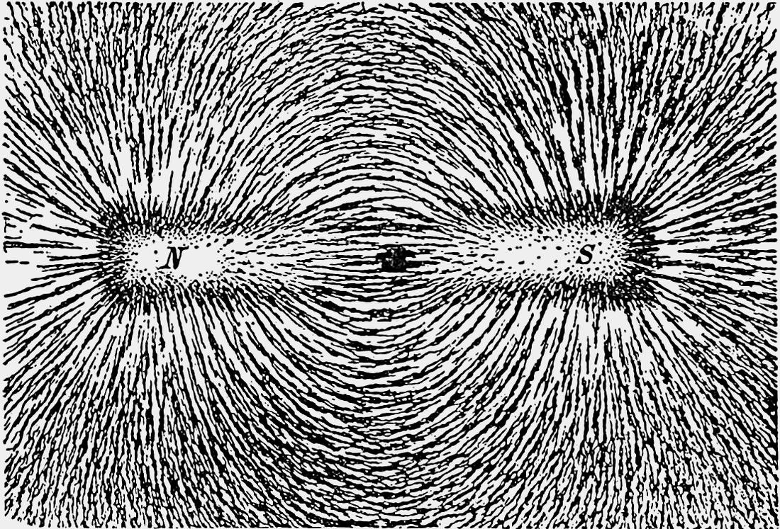
Now read the green magnetic-field diagram. Outside a bar magnet the conventional direction is north to south; through the magnet it returns from south to north, forming closed loops. A compass has its own magnetized needle: the needle’s north-seeking end points along the local field. This direction convention is different from the electric positive-test-charge convention. North and south are magnetic pole names, not electric plus and minus signs.
The direction changes with position around the magnet, so a compass on one side need not point the same way as a compass elsewhere. The chosen field lines never cross in a simple field drawing because the field has one direction at a location. The iron-filings photograph shows a physical response and approximate pattern; the labeled diagram supplies directions and the closed-loop model that the photograph alone cannot show.
Cutting a magnet does not produce a lone north pole and a lone south pole. Each piece remains a magnet with both poles. This is an explanation model, not a suggested cutting activity. Attraction to ordinary steel is also different from comparing two marked magnetic poles: either end of a bar magnet can attract suitable steel.
Pause and explain
Can attraction to a steel piece identify a magnet’s north pole?
Check your reasoning after answering
No. Either pole can attract a suitable steel piece. Compare with a known marked magnet or another appropriate reference to identify the pole.
Part 4 · Make a fair distance investigation
Keep the objects, orientation, and measurement method comparable while changing separation. Record a measurable outcome such as force from supplied sensor data. Counting attracted items can be a useful rough comparison but also depends on arrangement and cannot give a universal force law.
Read the visual model
What must stay comparable when testing the effect of separation?
Visual reasoning — after your attempt
Use the same source, test object, orientation, and measuring method. Change separation deliberately and repeat observations to check variation.
A supplied data set may show weaker force at greater gaps. Conclude only for the tested pair and range. If orientation changes with distance, the investigation has changed two factors and cannot isolate separation as clearly.
In the supplied graph the independent variable is gap, measured in centimetres (cm). The vertical axis is force in millinewtons (mN): 1 mN is one thousandth of a newton. The three points are 12, 6 and 3 mN at 1, 2 and 3 cm. Read the trend and units before making a claim. The line segments help the eye connect records; they are not measurements between the points. These mN values are a separately labeled illustrative dataset; the initial evidence case used arbitrary response units rather than a calibrated force scale.
From 1 to 2 cm this particular supplied force halves, but that does not prove a universal distance rule for magnets. Magnet shape, orientation and the test object affect the relationship. The inverse-square rule for ideal isolated electric point charges is a different model; it must not be silently applied to bar magnets. Repeat each gap and record variation before drawing a stronger conclusion.
Pause and explain
What must stay comparable when testing the effect of separation?
Check your reasoning after answering
Use the same source, test object, orientation, and measuring method. Change separation deliberately and repeat observations to check variation.
Field strength and stored energy
The gap between interacting objects can affect force, while rearranging them can also change stored energy in the two-object system.
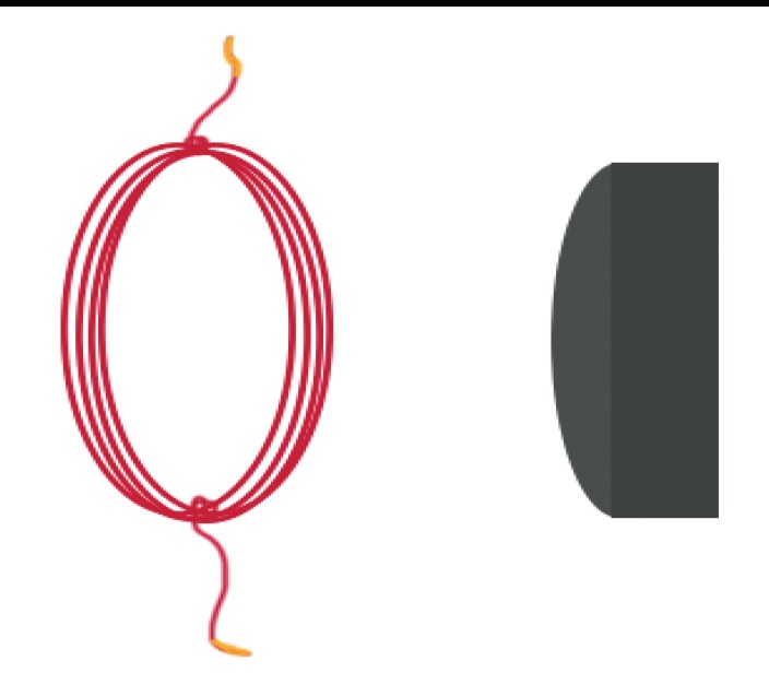
Current means the rate of electric-charge flow through a circuit, measured in amperes (A). A coil is wire wound into repeated turns. Together they make a useful cause-and-effect model: current through the turns produces a magnetic field, so the coil can act as an electromagnet. An iron core may strengthen its response. Increasing turns and increasing current are different changes and must be tested separately. The labeled schematic shows the idea; no homemade energized coil is needed.
A coil is wire arranged in turns. Current through a coil can produce a magnetic influence, making an electromagnet. Supplied coil records can test how turns, current and separation affect a response. A clip-lift count is a proxy, an indirect indicator, for performance and is not force in newtons. Do not infer a universal proportional rule from a short table or change coil turns and current together and call that an isolated comparison.
Potential energy belongs to the interacting arrangement, not a mysterious substance held by one object alone. Pushing repelling magnets closer can require work on the two-magnet system and increase its stored energy; releasing can transfer energy into motion and other paths. For an attractive pair, separating it can similarly require work and increase the store. Keep orientation and reference condition explicit before comparing arrangements.
Electric, magnetic and gravitational examples can all be modeled as forces acting across gaps with arrangement-dependent potential energy. A charged balloon and nearby hair illustrate electric interactions without creating new charge; charges are transferred or redistributed. A field model uses responses of a suitable test object to represent influence at different locations. It is not a line of material connecting the objects. A claim that effects require air can be tested against magnetic interaction across a vacuum, distinct from ordinary sound.
Follow the speaker cutaway: a fixed magnet provides a field, and current in a movable coil makes an interaction that can push the coil. The cone is attached to the coil. Changing current changes the force and lets the cone vibrate; the cone then makes the surrounding air vibrate. This is the chain that connects electric input, magnetic interaction, motion and sound. A diagram should explain the parts and connections, not merely label the word magnet.
For the additional illustrative turns investigation, current is held fixed and the trial clip counts are 3, 3, 4 for 10 turns; 5, 5, 6 for 20 turns; and 6, 7, 6 for 30 turns. Means are about 3.33, 5.33 and 6.33. Counts vary, so increased mean lifting performance does not prove exact proportionality or give force in newtons. These records test turns; the supplied evidence table separately tests current using matched turns.
Evidence to interpret
| Coil turns | Current (A) | Clip-lift count (illustrative) |
|---|---|---|
| 10 | 0.2 | 3 |
| 20 | 0.2 | 5 |
| 20 | 0.3 | 7 |
Use this method safely
Use supplied coil data; do not wind or energize homemade coils, use mains electricity or handle small powerful magnets. Any optional magnet observations use large classroom magnets with adult guidance.
Explain and apply
Use the coil records to ask an investigable question about each changed factor. Then draw a repelling-magnet energy model and contrast the work needed for separating an attractive pair.
- Isolate turns/current using the proper records.
- Distinguish proxy measurement from force.
- Model potential energy, orientation and work.
Reasoning and marking guidance — after your attempt
At fixed 0.2 A, changing turns from 10 to 20 raises the illustrative lift count 3→5; at fixed 20 turns, current 0.2→0.3 A changes it 5→7. These proxy outcomes support questions and a bounded trend, not a direct calibrated force law. Moving repelling magnets closer requires input work; separating attracting magnets can require input work instead. Energy is associated with the pair’s arrangement and can transfer into later motion.
Apply the whole unit · Interpret an interaction experiment
Illustrative measurements for the same magnet and test piece with fixed orientation: gaps 1, 2, and 3 cm give forces 0.8, 0.3, and 0.1 N. In a separate case, a charged rod attracts uncharged paper.
Your task
Graph the magnetic results, describe the supported trend, and explain why the data cannot establish a universal formula. Draw a charge-redistribution model for the paper without giving it an unsupported net charge.
What your response should show
- Use the supplied observations and measurements accurately; include units where needed.
- Explain the science behind your answer, rather than giving only a number or label.
- Show a labeled model, calculation, or evidence comparison as requested.
- State an assumption or limitation and suggest a useful next measurement.
Response guidance — after your attempt
The force decreases across the tested gaps, but three measurements for one setup do not establish a universal inverse-distance formula. Label axes and units and keep orientation fixed. In the paper, charges redistribute so the nearer region interacts more strongly; the total can remain neutral. Attraction alone is insufficient to claim opposite net charge.
Scientific references and adapted teaching resources
- OpenSciEd 8.1 Contact Forces — public unit overview
- OpenSciEd 8.3 Forces at a Distance — public unit overview
- OpenSciEd instructional model — storyline routines
- Creative Commons Attribution 4.0 — middle-school material license
- OpenSciEd 8.3 Lesson 3 — Framing Hypotheses (public handout)
- OpenStax: electric field direction and drawing conventions
- OpenStax: magnetic fields, closed loops and compass direction
Parent / teacher teaching notes
Keep electric charge signs and magnetic pole labels separate. Use the supplied measurements for quantitative work. Avoid small powerful magnets and any experiment involving wall electricity. Adaptation credit: OpenSciEd middle-school teaching routines and public task structures by OpenSciEd, CC BY 4.0. This independent version adds original explanatory text, data and figures, terminology support and a home-study schedule. It does not reproduce the complete teacher editions or their classroom validation. The illustrated study “Field strength and stored energy” is required curriculum content. Teach it before the associated application or distribute it over the assigned unit sessions; it is not an optional enrichment. Its practice/review/quiz response provides evidence of understanding. Model/data work must not be recorded as an actual physical experiment.
The key idea
Electric and magnetic forces can act through space; controlled tests reveal what changes their strength.
Worked examples
Example 1
- The same magnet, clip, and surface were used.
- The effect was observed at the shorter separation.
- Repeat the test to check reliability.
Example 2 · Worked application
- A neutral object has equal total positive and negative charges.
- The balloon's electric field can shift charge distribution slightly within the paper.
- The resulting polarization can produce net attraction without giving the paper a net charge.
Distinguish net charge from uneven distribution of charge.
Example 3
- The comb's field can slightly rearrange charges in the paper.
- Opposite charge closer to the comb can experience a stronger attraction than the farther like charge's repulsion.
Example 4 · Find and fix the mistake
- Test the claim against the stated conditions: Distinguish net charge from uneven distribution of charge.
- Certain materials can be magnetized by a nearby field without starting as permanent magnets; attraction alone is insufficient.
Distinguish net charge from uneven distribution of charge.
Example 5 · Field arrow versus force arrow
- Identify the field convention: it gives force direction for a positive test charge.
- A negative test charge responds in the opposite direction.
- Its force therefore points left, toward the positive source.
Changing the test-charge sign reverses force direction, not the defined field direction at that point.
Example 6 · Read a compass model
- Locate the compass on the outside field line.
- Follow the outside field direction from N to S.
- Above the middle in this symmetric drawing, the local tangent points right.
Do not label magnetic north as positive electric charge or assume every position has the same field direction.
Example 7 · Interpret the visual model
- Identify the represented objects, axes, labeled quantities and stated conditions before choosing a rule.
- A magnet can attract a suitable object before touching it. Compare the same objects at different distances. Do not assume every shiny metal is strongly attracted, because magnetic response depends on the material.
- It represents where and in what direction a source can influence suitable test objects. It does not show physical strings or prove identical force at every location.
Keep the model’s stated limits explicit: The blue arrows show electric-field direction, defined by the force on a small positive test charge. They point away from a positive source and toward a negative source. A negative test charge feels force opposite the field arrow. Lines represent a model at many positions, not strings or paths an object must follow. The drawing shows selected directions in a plane, not every field direction in three dimensions.
Avoid these mistakes
- A neutral object's attraction does not mean it had a net charge beforehand.
Check your understanding
A charged comb attracts small neutral paper pieces. Explain a model without assuming the paper gains a permanent charge.
Discuss the answer
Charge separation, or polarization, can produce a net attraction even while the paper remains neutral.
What happens to the poles when a bar magnet is cut into two pieces?
Discuss the answer
A field represents how an object could experience a force at a location without touching the source. Field diagrams use arrows to show direction and density of lines to suggest relative strength. The drawn lines are a model, not material strings filling space. Electric forces can attract or repel. Neutral objects can sometimes be attracted because their charges shift slightly within the material. Magnets have north and south poles, and ordinary cutting of a magnet makes two smaller magnets, each with both poles.
Return to the phenomenon
Illustrative tests use the same magnets and orientation with separations 1, 2 and 3 cm. Force magnitudes are 12, 6 and 3 arbitrary units. A paper barrier at 1 cm still gives 12 units. Identify evidence for an interaction across a gap, describe the distance trend and explain why the barrier does not prove a universal field law. Revise your first explanation using a named idea from the lesson. Mark the changed part and the evidence that supports it.
Compare explanations after your attempt
The objects affect one another without direct contact and remain coupled across the supplied paper barrier. The measured force decreases with separation in this range. These illustrative records do not establish a universal inverse-square rule for all magnet geometries or show that every barrier behaves like paper. A field is a model of the spatial influence, not a material stream of air.
What should we investigate next?
Which condition could be changed to test a remaining uncertainty in this explanation? State the predicted observation and what result would challenge your model.
Investigate, explain and revise
Use these tasks after the three teaching sessions as needed. Discuss an attempted explanation before opening response guidance; a matching sentence is less important than a supported mechanism.
Activity 1 · Explain the new evidence case
Use the visible scenario above, Parts 1–4 and your first notebook model. No outside reading or equipment is required.
Your task
Illustrative tests use the same magnets and orientation with separations 1, 2 and 3 cm. Force magnitudes are 12, 6 and 3 arbitrary units. A paper barrier at 1 cm still gives 12 units. Identify evidence for an interaction across a gap, describe the distance trend and explain why the barrier does not prove a universal field law. Write 100–150 words or give a labeled drawing with an equivalent oral explanation.
Success criteria
- Use two relevant stated records or conditions.
- Explain the mechanism rather than only repeat a definition.
- Label observation and inference.
- Name a changed model feature or a remaining uncertainty.
Hint
Read the stated boundary and conditions before selecting a relationship. The unit’s worked examples show intermediate steps.
Response guidance — discuss after your attempt
The objects affect one another without direct contact and remain coupled across the supplied paper barrier. The measured force decreases with separation in this range. These illustrative records do not establish a universal inverse-square rule for all magnet geometries or show that every barrier behaves like paper. A field is a model of the spatial influence, not a material stream of air.
Activity 2 · Read and extend the figure
Study the new labeled figure and its caption, then compare it with the associated teaching part.
Your task
Why not change the test magnet size between positions? Explain what each important label represents. Add one missing feature that would be needed for a different question, and explain why the original figure leaves it out.
Success criteria
- Answer the figure question with its stated labels.
- Connect the visual representation to the scientific idea.
- Identify a specific limitation from the caption.
- Propose a useful change without misrepresenting supplied evidence.
Hint
The three positions stand for separate tests with the same test object and orientation. The force magnitudes are illustrative and show decreasing strength over this tested range, not a universal formula. A mapped field describes how a suitable test object responds at different locations.
Response guidance — discuss after your attempt
That would change another cause of force, confounding the intended distance comparison. The three positions stand for separate tests with the same test object and orientation. The force magnitudes are illustrative and show decreasing strength over this tested range, not a universal formula. A mapped field describes how a suitable test object responds at different locations.
Words to know
- field
- A model describing the influence an object has in the space around it.
- repel
- Push apart.
- controlled variable
- A factor kept the same during a comparison.
- model
- A representation that explains selected features and makes predictions; it leaves other details out.
- evidence
- Relevant observations or records used to support or challenge a claim.
- system boundary
- The chosen limit separating the objects being studied from their surroundings.
- assumption
- A condition taken as true for a model or calculation and needing to be checked against the case.
- electric charge
- A property responsible for electric interactions. In this introductory model, excess electrons give an object net negative charge and an electron deficit can give it net positive charge.
- polarization
- A slight shift or separation of positive and negative charge within material; the whole object can remain electrically neutral.
- current
- The rate of electric-charge flow through a chosen part of a circuit, measured in amperes (A).
- coil
- Wire wound into repeated turns. Current through the turns produces a magnetic field.
- electromagnet
- A magnet produced by electric current, often using a wire coil and an iron core.
- compass
- An instrument with a magnetized needle; its north-seeking end points along the local magnetic field.
In the real world
Exit check
Why not change the test magnet size between positions? Explain the relevant mechanism and one model limitation.
Check your explanation after answering
That would change another cause of force, confounding the intended distance comparison. The three positions stand for separate tests with the same test object and orientation. The force magnitudes are illustrative and show decreasing strength over this tested range, not a universal formula. A mapped field describes how a suitable test object responds at different locations.
Explain your reasoning without notes. If a key idea is missing, revisit the lesson and try again.