Electricity, Magnetism & Circuits — Print · Physics & Environmental Science, Grade 12
Relate charge, fields, voltage, circuits, induction, stored energy, and electrical power.
Printable chapter lessons and review.
Electric Charge & Fields
Learning goals
- I can explain that charge comes in two types, is quantized, and is conserved.
- I can use Coulomb's law (F = kq₁q₂/r²) to calculate the electrostatic force between two charges.
- I can describe an electric field, calculate it with E = F/q, and sketch its field lines.
Readings for this unit
Before this unit
Charge signs and inverse-square interaction.
Use the detailed parent plan: two core 50–60-minute sessions per focused unit, with a third assigned for selected calculation/modeling topics. First study the core explanation and Parts 1–2 with their figures/checks; next study Parts 3–4, the whole-unit application, worked cases, varied practice and exit check. Attempt reasoning before opening guidance. Extend time when actual understanding requires it; investigations and chapter assessments have separate sessions.
Start with something to explain
Can a charge-free location still have an electric field?
Illustrative evidence case. A small test charge placed between remote sources experiences a force.
Notice and wonder
Record two observations using the stated quantities or relationships. Keep observations separate from possible causes. Write one question that a new measurement could help answer.
Can a charge-free location still have an electric field?
Your first model
Separate source charges, field at the location and force on the test.
Build the language from the idea
- electric charge
- A fundamental property of matter that comes in two types, positive and negative, measured in coulombs (C).
- Coulomb's law
- The rule that the force between two charges is proportional to the product of the charges and inversely proportional to the square of the distance: F = kq₁q₂/r².
- electric field
- The region around a charge where another charge would feel a force; its strength is the force per unit charge, E = F/q, in N/C.
- conductor
- A material such as copper in which some electrons are free to move, so charge flows through it easily.
- insulator
- A material such as rubber or glass whose electrons are locked in place, so charge does not flow through it.
Everything you touch is built from atoms, and buried inside every atom is electric charge. Protons in the nucleus carry positive charge, electrons carry an equal-sized negative charge, and an atom with matching numbers of each is electrically neutral. Charge is quantized — it always comes in whole-number multiples of the elementary charge, e = 1.6 × 10⁻¹⁹ coulombs — so you can strip away three electrons or add a thousand, but never half of one. Charge is also conserved: it is never created or destroyed, only moved from one object to another. When you rub a balloon on your hair, you are not making charge, just transferring electrons from the hair to the balloon.
The single most important rule of charge is short: like charges repel, and opposite charges attract. Two negatives push apart, two positives push apart, but a positive and a negative pull together. This is strikingly different from gravity, which only ever attracts — electric forces come in both flavors, and that two-sidedness is exactly what makes circuits, chemistry, and electronics possible. It also explains everyday static electricity: a comb that has stolen electrons becomes negatively charged and can lift tiny bits of paper by attracting their positive regions.
Conductors have charge carriers that can move through the material under suitable conditions. Ordinary insulators strongly restrict sustained charge conduction but can still polarize, accumulate surface charge, leak, or break down at sufficiently large fields. Conducting versus insulating behavior depends on material, temperature, and operating conditions; it is not a claim that every electron is perfectly fixed or that an arbitrary insulating layer guarantees safe handling.
To go beyond 'they attract or repel' and actually predict the force, we use Coulomb's law: F = k·q₁·q₂ ÷ r², where the charges are in coulombs, the distance r is in meters, and the constant k ≈ 9 × 10⁹ N·m²/C². Two features matter most. Bigger charges mean a bigger force, in direct proportion. And because r is squared in the denominator, the force falls off fast with distance — double the separation and the force drops to a *quarter*, triple it and the force drops to a *ninth*. This inverse-square shape is the exact same mathematical fingerprint that Newton's law of gravitation carries, which is why the two laws are so often taught side by side.
An electric field describes local force per sufficiently small positive test charge, E=F/q, in N/C. A source produces a field whether or not that test is present, and a negative test feels force opposite E. Field lines point away from positive and toward negative sources; their density can encode relative magnitude under a consistent drawing convention. Approximately uniform parallel-plate fields apply away from edge effects. Changes in sources propagate physically rather than implying instantaneous influence across arbitrary distances.
These ideas are the bedrock of the entire unit and of modern technology. A moving stream of charge is nothing more than an electric current, the subject of the next lesson, and the push that drives it is a difference in electric potential built from these very fields. Electric fields steer the electrons that paint an old TV screen, sort the toner in a laser printer, trigger the spark in an engine, and register the touch of your finger on a phone. Learn to reason about charge, Coulomb's law, and fields, and you hold the key that unlocks everything from a single spark to the power grid.
Model check: Field exists as a model independent of the particular small test charge. F=qE=.002N along the field; a negative charge would reverse direction.
Build your understanding
Use the detailed parent plan: two core 50–60-minute sessions per focused unit, with a third assigned for selected calculation/modeling topics. First study the core explanation and Parts 1–2 with their figures/checks; next study Parts 3–4, the whole-unit application, worked cases, varied practice and exit check. Attempt reasoning before opening guidance. Extend time when actual understanding requires it; investigations and chapter assessments have separate sessions.
Part 1 · Account for charge and transfer
Electric charge is a signed property whose total is conserved in the selected complete system. In ordinary contact charging of solids, electrons can transfer while nuclei remain bound. A body that loses an electron becomes more positive; one that gains it becomes more negative. The dots here track selected electrons, not every particle in an initially neutral solid. Include the omitted positive background before interpreting net charge from the picture.
Read the visual model
Identify the labeled structures and units, then trace the arrows or compare values under the caption’s stated conditions. Separate the displayed evidence from a further inference. Write your reasoning before opening the guidance.
Why does electron loss make a body more positive?
Visual reasoning — after your attempt
Its negative electron count falls while its positive nuclear charge remains, leaving a positive imbalance.
Electric charge can be positive or negative and is conserved in an appropriate complete system account. Ordinary charging often transfers electrons between materials; it does not create new protons inside atoms. A neutral object contains charges whose totals balance, not an absence of charged particles.
Removing electrons leaves a positive net charge. Induction can redistribute charge without immediate contact transfer, so distinguish separation from net addition.
Pause and explain
Does neutral mean there are no electrons?
Check your reasoning after answering
No. Neutrality means total positive and negative charge balance; charged constituents remain present.
Part 2 · Apply Coulomb’s law to a stated geometry
Coulomb’s law gives the electrostatic force magnitude between ideal point charges as k|q₁q₂|/r². Like signs repel and unlike signs attract along the joining line. Use center separation and compatible coulomb/meter units. Extended conductors can redistribute charge, so a single point-charge formula is not automatically valid for every charged object geometry. Equal opposite interaction forces act on the two different charges, consistent with Newton’s third law.
Read the visual model
Identify the labeled structures and units, then trace the arrows or compare values under the caption’s stated conditions. Separate the displayed evidence from a further inference. Write your reasoning before opening the guidance.
If separation triples with charges unchanged, what happens to force magnitude?
Visual reasoning — after your attempt
It becomes 1/9 as large under the point-charge model.
For point charges or suitable symmetric distributions, force magnitude is k|q₁q₂|/r². Direction follows attraction for opposite signs and repulsion for like signs. Use center separation and consistent units; extended nearby objects can need a more detailed charge-distribution account.
Doubling both charges multiplies force by four at fixed separation, while doubling separation divides it by four. Conditions determine the comparison.
Pause and explain
Why does the absolute-value formula not identify force direction?
Check your reasoning after answering
It calculates magnitude. Charge signs and geometry are still needed to assign the attraction or repulsion direction.
Part 3 · Distinguish field from force on a test charge
An electric field assigns force per positive test charge: E=F/q for a sufficiently small nonperturbing test. A positive source has outward field direction; a negative source has inward direction. A positive test charge feels force along E while a negative one feels force opposite E. Field units N/C differ from force units N. Field arrows are local direction indicators, not paths every released charge must follow.
Read the visual model
Identify the labeled structures and units, then trace the arrows or compare values under the caption’s stated conditions. Separate the displayed evidence from a further inference. Write your reasoning before opening the guidance.
If E points right, which way is force on an electron?
Visual reasoning — after your attempt
Left, because the electron’s charge is negative and F=qE.
Electric field describes force per positive test charge: E=F/q in a suitable small-test-charge limit. Its direction is the force direction for a positive charge. A negative charge experiences force opposite the field, so field arrows are not automatically force arrows for every particle.
The field near a negative source charge points toward it. A positive test charge accelerates toward the source, while a negative one is repelled.
Pause and explain
Does changing the test-charge sign reverse the source field?
Check your reasoning after answering
No. The field from the source is unchanged in the small-test approximation, but the force qE changes direction.
Part 4 · Add fields as vectors and inspect assumptions
Field superposition adds source-field vectors at the same location. At the midpoint of equal positive charges, equal opposite fields cancel even though neither source contribution is zero. Electric potential is a scalar sum and need not vanish there. Away from the symmetry point, calculate each distance and direction before combining components. A zero net field also does not mean that all nearby points have zero field or that arbitrary motion remains unchanged indefinitely.
Read the visual model
Identify the labeled structures and units, then trace the arrows or compare values under the caption’s stated conditions. Separate the displayed evidence from a further inference. Write your reasoning before opening the guidance.
At this midpoint, is the field from each source individually zero?
Visual reasoning — after your attempt
No. Both are nonzero and equal in magnitude but opposite in direction.
Fields from multiple sources add vectorially in the usual electrostatic model. Equal source magnitudes do not guarantee cancellation at every point; directions and distances matter. A test charge large enough to redistribute source charges can alter the system and invalidate a simple fixed-source account.
Between equal like charges, fields cancel at the midpoint; between equal opposite charges, their midpoint fields reinforce.
Pause and explain
Why can equal charges give a nonzero combined field?
Check your reasoning after answering
Equal contributions can point in the same direction or arise at unequal distances. Vector geometry, not magnitude alone, determines the sum.
Apply the whole unit · Predict field and force from a negative source
Illustrative fixed source charge −3.00 μC and positive test charge +2.00 μC are 0.300 m apart in a vacuum point-charge model. Use k=9.00×10⁹ N·m²/C².
Your task
Calculate field at the test location and force on it, show their directions, and predict the effect of replacing the test charge with −2.00 μC without moving the source.
What your response should show
- Define the system, quantities, units, and relevant conditions before selecting a model.
- Show intermediate calculations or a labeled evidence account, including signs or denominators.
- Explain how the supplied evidence supports the conclusion rather than reporting only an answer.
- Identify a meaningful uncertainty, model limit, or measurement needed to test the conclusion.
Response guidance — after your attempt
Source field magnitude=9.00×10⁹×3.00×10⁻⁶/0.300²=3.00×10⁵ N/C, toward the source.
Positive-test force magnitude=2.00×10⁻⁶×3.00×10⁵=0.600 N, toward the source.
With a negative test charge, field is unchanged but force points away, with the same magnitude.
The result distinguishes a source property at a location from the response of a selected charge. It assumes fixed point charges and a test charge that does not alter the source arrangement. A real conducting distribution may rearrange, so geometry and source constraints would need examination.
Scientific references and source-model foundations
Parent / teacher teaching notes
Ask students to draw field and test-force arrows separately. Require conversion of microcoulombs before substitution. Ask the learner to explain each symbol, axis, unit and arrow before calculating. Calculated examples, supplied illustrative records and actual historical observations are labeled separately. Selected public OpenSciEd middle-school source figures are foundation examples, not complete high-school editions or an endorsement; all advanced explanations are supplied locally.
A Bohr model of an atom showing a positively charged nucleus of protons and neutrons with negatively charged electrons orbiting around it.
The key idea
Charge is quantized and conserved; like charges repel and opposites attract with a force given by Coulomb's law F = kq₁q₂/r²; every charge sets up an electric field E = F/q that points away from positive and toward negative charge.
Coulomb's Law
F = k·q₁·q₂ ÷ r²
F is the electrostatic force in newtons (N); q₁ and q₂ are the charges in coulombs (C); r is the separation in meters (m); k ≈ 9 × 10⁹ N·m²/C².
Electric Field Strength
E = F ÷ q
E is the electric field in newtons per coulomb (N/C); F is the force on a small test charge q. For a point charge this also equals E = k·q ÷ r².
Worked examples
Example 1
- Write Coulomb's law: F = k·q₁·q₂ ÷ r².
- Substitute: F = (9 × 10⁹)(3 × 10⁻⁶)(4 × 10⁻⁶) ÷ (0.6)².
- The top is 9 × 10⁹ × 12 × 10⁻¹² = 0.108; divide by 0.36.
Example 2 · Worked application
- F=k×absolute(q₁q₂)/r².
- Replacing r by 2r increases the denominator fourfold.
- Direction depends on charge signs.
Distance is center-to-center under the point-charge model.
Example 3
- Use the definition of electric field: E = F ÷ q.
- E = 0.3 ÷ (2 × 10⁻⁶).
- = 150,000.
Example 4 · Find and fix the mistake
- Test the claim against the stated conditions: Distance is center-to-center under the point-charge model.
- Field is force per unit positive test charge; actual force depends on test-charge value and sign.
Distance is center-to-center under the point-charge model.
Example 5 · Reason from the visual model
- An electric field assigns force per positive test charge: E=F/q for a sufficiently small nonperturbing test. A positive source has outward field direction; a negative source has inward direction. A positive test charge feels force along E while a negative one feels force opposite E. Field units N/C differ from force units N. Field arrows are local direction indicators, not paths every released charge must follow.
- Left, because the electron’s charge is negative and F=qE.
Original radial field directions for a positive point source; equal arrow lengths do not depict radial field magnitude decay.
Avoid these mistakes
- Field exists as a model independent of the particular small test charge.
Check your understanding
A+2microC test charge in 1000N/C field experiences what force?
Discuss the answer
F=qE=.002N along the field; a negative charge would reverse direction.
Return to the phenomenon
Return to the initial case. Can a charge-free location still have an electric field? Revise your drawing or explanation using two named ideas and one stated limitation.
Compare explanations after your attempt
Fields arise from sources elsewhere; force depends on test charge sign and magnitude, and fields combine as vectors.
What should we investigate next?
Which comparison would test a remaining uncertainty? State what you would change, keep comparable and measure.
Investigate, calculate and revise
Keep a first model and an evidence-supported revision. Attempt each task before opening guidance; all required explanations and supplied-data routes are available locally.
Activity 1 · Return to the opening case
Use the opening phenomenon, unit definitions and explained Parts 1–4.
Your task
Return to the initial case. Can a charge-free location still have an electric field? Revise your drawing or explanation using two named ideas and one stated limitation.
Success criteria
- Use the stated observations and appropriate units.
- Connect a labeled model with the physical/environmental mechanism.
- State assumptions and an evidence limitation.
- Explain a substantive revision or next test.
Hint
Keep object/material identity, material transfer and energy account distinct.
Response guidance — discuss after your attempt
Fields arise from sources elsewhere; force depends on test charge sign and magnitude, and fields combine as vectors.
Activity 2 · Transfer to a changed case
Cover the worked answer and use the explained models, relationships and notebook.
Your task
A+2 μC test charge in a uniform 500 N/C field points east. Find its force. What force acts on a−3 μC test at the same location?
Success criteria
- Use the stated measurements or conditions, with correct units.
- Connect the result to the physical or environmental mechanism or evidence relationship.
- Identify the assumption, model limit or further evidence requested.
Hint
Name known quantities and conditions, show intermediate steps and check conservation.
Response guidance — discuss after your attempt
F=qE gives+0.0010 N east for+2 μC and−0.0015 N, i.e.west, for−3 μC. The field is unchanged in the ideal nonperturbing-test model.
Words to know
- electric charge
- A fundamental property of matter that comes in two types, positive and negative, measured in coulombs (C).
- Coulomb's law
- The rule that the force between two charges is proportional to the product of the charges and inversely proportional to the square of the distance: F = kq₁q₂/r².
- electric field
- The region around a charge where another charge would feel a force; its strength is the force per unit charge, E = F/q, in N/C.
- conductor
- A material such as copper in which some electrons are free to move, so charge flows through it easily.
- insulator
- A material such as rubber or glass whose electrons are locked in place, so charge does not flow through it.
Coulomb weighed an invisible force with a twisted thread
How do you measure a force too weak to feel? In 1785, French engineer Charles-Augustin de Coulomb built a torsion balance: a light rod hung from a thin fiber, with a charged ball on one end. Bringing a second charged ball nearby made the rod twist, and the amount of twist revealed the force with astonishing precision. By varying the charges and distances, Coulomb showed the force is proportional to the product of the charges and falls off as the square of the distance — the inverse-square law we now write F = kq₁q₂/r². The unit of charge, the coulomb, is named in his honor, and the same delicate torsion-balance trick was later used to weigh the gravitational constant.
You can't have half an electron: Millikan's oil drops
The idea that charge is quantized — that it comes only in whole multiples of a smallest unit — was nailed down between 1909 and 1913 by Robert Millikan in his famous oil-drop experiment. He sprayed tiny charged oil droplets between two charged plates and balanced gravity against the electric force to measure the charge on each drop. Every charge he found turned out to be a whole-number multiple of the same tiny value, e ≈ 1.6 × 10⁻¹⁹ coulombs — the elementary charge. There simply were no in-between values. This is why you can transfer one electron or a billion, but never a fraction of one, and it earned Millikan the 1923 Nobel Prize in Physics.
Coulomb's law and Newton's gravity: identical shape, wildly different strength
Look at Coulomb's law and Newton's law of gravitation side by side and they are mathematical twins — both are inverse-square laws where the force depends on the product of two 'source' quantities (charge for one, mass for the other) divided by distance squared. But their strengths are worlds apart: between two electrons, the electric repulsion is about 10⁴² times stronger than their gravitational attraction. So why does gravity rule planets and galaxies while electricity seems to hide? Because matter is almost perfectly neutral — equal positive and negative charge cancel out over any large object — while mass only ever adds up. Gravity wins the cosmos by default, simply because charge cancels and mass never does.
Lightning is charge separation on a colossal scale
A thundercloud is a Coulomb's-law laboratory kilometers tall. Violent updrafts and colliding ice particles strip electrons from one region and pile them into another, separating enormous amounts of charge and building potential differences of hundreds of millions of volts between cloud and ground. When the electric field grows strong enough to rip electrons off air molecules, the air suddenly becomes a conductor and a lightning bolt discharges it all in a few thousandths of a second. Benjamin Franklin's famous (and extremely dangerous) 1752 kite work argued that lightning was simply electricity, and led directly to the lightning rod — a pointed conductor that quietly bleeds charge away and gives a strike a safe path to ground.
In the real world
Laser printers and photocopiers use Coulomb's law in action: a charged drum attracts oppositely charged toner powder exactly where the image should appear, then presses it onto the paper.
Exit check
A+2microC test charge in 1000N/C field experiences what force?
Check your explanation after answering
F=qE=.002N along the field; a negative charge would reverse direction.
Explain your reasoning without notes. If a key idea is missing, revisit the lesson and try again.
Current, Voltage & Resistance
Learning goals
- I can define electric current as the rate of flow of charge and calculate it with I = Q/t.
- I can explain voltage as the energy delivered per unit of charge, using V = W/Q.
- I can describe resistance and the wire properties that increase or decrease it.
Readings for this unit
Before this unit
Charge per time and energy per charge.
Use the detailed parent plan: two core 50–60-minute sessions per focused unit, with a third assigned for selected calculation/modeling topics. First study the core explanation and Parts 1–2 with their figures/checks; next study Parts 3–4, the whole-unit application, worked cases, varied practice and exit check. Attempt reasoning before opening guidance. Extend time when actual understanding requires it; investigations and chapter assessments have separate sessions.
Start with something to explain
Why can a battery have a voltage when a switch is open?
Illustrative evidence case. The open circuit has separated terminals but almost no steady conduction path.
Notice and wonder
Record two observations using the stated quantities or relationships. Keep observations separate from possible causes. Write one question that a new measurement could help answer.
Why can a battery have a voltage when a switch is open?
Your first model
Distinguish a two-point voltage from a branch charge-flow rate.
Build the language from the idea
- electric current
- The rate at which electric charge flows past a point, I = Q/t, measured in amperes (A).
- ampere (A)
- The SI unit of current; one ampere is one coulomb of charge flowing per second.
- voltage (potential difference)
- The electrical energy delivered to each unit of charge, V = W/Q, measured in volts (V).
- resistance
- The opposition a material offers to the flow of current, measured in ohms (Ω).
- resistivity
- A property of a material itself that sets how strongly it resists current; it, along with a wire's length and thickness, determines the wire's resistance.
In the last lesson charges sat still; now we set them marching. Electric current is simply the rate at which charge flows past a point in a circuit, written I = Q ÷ t — the amount of charge Q, in coulombs, divided by the time t, in seconds. Its unit is the ampere (A), and one amp means one full coulomb of charge (about 6.2 × 10¹⁸ electrons) streaming past every second. By long-standing convention we describe current as flowing from the positive terminal of a battery to the negative one, even though in a metal wire it is actually the negative electrons drifting the opposite way.
Potential difference, or voltage, is energy per charge between two points, in J/C. A steady ideal 9 V source supplies 9 J per coulomb crossing its rise. In an ordinary resistive circuit an electric field supports charge drift, but induction and other devices require their own source model; “voltage always causes current” is not a universal definition. An open circuit can have voltage with almost no steady current, and charge-flow rate also depends on the actual network and operating conditions.
The third member of the trio is resistance, the opposition a material offers to the flow of charge, measured in ohms (Ω). As charge pushes through a material, it collides with the vibrating atoms of the lattice and loses energy, which is why a resistor warms up. Resistance is what converts electrical energy into the heat of a toaster, the glow of a bulb filament, and the warmth of a hair dryer — all deliberately built to resist current so that the energy shows up as heat and light.
For an ideal uniform ohmic wire, R=ρL/A, so a longer wire increases resistance and a larger cross-sectional area reduces it when material and conditions remain fixed. Resistivity depends on material and temperature. Many metals increase in resistivity as they warm, but semiconductors and other materials can behave differently. The long-thin-hot ranking is therefore a conditional metal-wire example, not a universal law for every conductor.
The classic way to feel how these three quantities relate is a water-pipe analogy. Picture water pumped around a loop of pipe: the voltage is like the pressure from the pump that pushes the water, the current is like the amount of water actually flowing past each second, and the resistance is like a narrow, constricted section of pipe that holds the flow back. Raise the pressure (voltage) and more water flows; pinch the pipe tighter (more resistance) and less water flows. The analogy is not perfect, but it captures the essential cause-and-effect: voltage pushes, resistance restrains, and current is the flow that results.
These three ideas — current, voltage, and resistance — are the vocabulary of every electrical device on Earth, and they do not act independently. Push harder (more voltage) and current rises; add more resistance and current falls. That precise relationship is captured by Ohm's law, the centerpiece of the next lesson, which ties all three together into a single equation you can solve. Master what current, voltage, and resistance each *mean* here, and Ohm's law becomes not a formula to memorize but a sentence you already understand.
Model check: Current does not mean charges are consumed; a component transfers energy while charge is conserved. I=Q/t=3 A; conventional current direction is positive-charge flow.
Build your understanding
Use the detailed parent plan: two core 50–60-minute sessions per focused unit, with a third assigned for selected calculation/modeling topics. First study the core explanation and Parts 1–2 with their figures/checks; next study Parts 3–4, the whole-unit application, worked cases, varied practice and exit check. Attempt reasoning before opening guidance. Extend time when actual understanding requires it; investigations and chapter assessments have separate sessions.
Part 1 · Define current as a charge-flow rate
Electric current is the net rate of charge crossing a selected section, I=ΔQ/Δt. One ampere is one coulomb per second. Conventional current follows positive-charge flow; conduction electrons in a metal drift in the opposite direction. The wire already contains mobile carriers, so a battery does not have to send one electron around the whole circuit before a distant lamp can respond. Distinguish carrier drift from electromagnetic signal propagation.
Read the visual model
Identify the labeled structures and units, then trace the arrows or compare values under the caption’s stated conditions. Separate the displayed evidence from a further inference. Write your reasoning before opening the guidance.
What current corresponds to 6 C crossing in 3 s?
Visual reasoning — after your attempt
I=2 A in the chosen conventional direction.
Conventional current has the direction of positive charge flow. In metal conductors, electron drift is opposite that direction. Current I=ΔQ/Δt describes rate, not a stored amount of charge. Charge already exists in the circuit materials; a component transfers energy without using up charge.
A 2 A steady current corresponds to 2 C passing a selected cross-section each second. The same sustained series current can pass through different components.
Pause and explain
Does a resistor use up the current flowing through it?
Check your reasoning after answering
No. In a steady series circuit charge flow continues; energy transfers in the resistor while charge conservation constrains the current.
Part 2 · Interpret potential difference as energy per charge
Potential difference, or voltage, is a change of electric potential energy per unit charge: ΔV=ΔU/q in the stated electrostatic account. A 6 V potential rise corresponds to 6 J per coulomb for a positive charge. Voltage is measured between two points, whereas current is through a branch. A large voltage can exist across an open switch with essentially no steady current; the quantities are related through the actual circuit rather than interchangeable definitions.
Read the visual model
Identify the labeled structures and units, then trace the arrows or compare values under the caption’s stated conditions. Separate the displayed evidence from a further inference. Write your reasoning before opening the guidance.
How much energy is transferred per 4 C across a 6 V load drop?
Visual reasoning — after your attempt
24 J in magnitude, assuming the specified potential drop and charge transfer.
Voltage is electric potential difference, with units J/C. It tells how electric energy changes per charge between points, not how many charges are present or their drift speed. A circuit needs both a potential difference and an appropriate conducting path for sustained current in the basic model.
A 12 V difference corresponds to 12 J per coulomb for the electrical transfer account. Different resistances can give different currents at that same voltage.
Pause and explain
Why cannot voltage alone specify current?
Check your reasoning after answering
The circuit’s material properties, geometry, and component behavior also determine the resulting current.
Part 3 · Use resistance under appropriate conditions
Resistance relates voltage across a component to current through it; an ohmic model uses constant R so V=IR and the current–voltage graph is linear through the origin. Many real devices are nonohmic or change resistance as they heat. A curved graph does not violate energy conservation; it means a single constant-R approximation is inadequate. Read whether the vertical axis is current or voltage before interpreting the slope as R or 1/R.
Read the visual model
Identify the labeled structures and units, then trace the arrows or compare values under the caption’s stated conditions. Separate the displayed evidence from a further inference. Write your reasoning before opening the guidance.
What current does this 10 Ω model predict at 5 V?
Visual reasoning — after your attempt
0.50 A under the same operating conditions.
For an ohmic component under fixed conditions, V=IR with approximately constant resistance. Resistance can depend on material, length, cross-section, and temperature. Real lamps and semiconductor devices can be nonohmic, so a single resistance value may not describe every operating point.
For an ideal uniform wire, R=ρL/A; doubling length doubles resistance if material, area, and conditions remain fixed.
Pause and explain
Is V=IR a proof that every component has constant resistance?
Check your reasoning after answering
No. R can be an operating-point ratio for a nonohmic component; an ohmic model requires a suitable approximately linear relationship under the stated conditions.
Part 4 · Connect charge flow to energy transfer
Electrical power in a steady DC component is P=VI. This follows from joules per coulomb multiplied by coulombs per second. A load transfers electrical energy into other forms while charge is conserved; it does not use up current so that less charge must return. The same current through components in a steady series path can accompany different voltage drops and powers. Use actual branch voltage and current rather than an unrelated source label.
Read the visual model
Identify the labeled structures and units, then trace the arrows or compare values under the caption’s stated conditions. Separate the displayed evidence from a further inference. Write your reasoning before opening the guidance.
What energy does the displayed 3 W load transfer in 20 s?
Visual reasoning — after your attempt
E=Pt=60 J if its power remains 3 W.
For a constant voltage across a component and steady current, transferred electrical energy can be VQ=VIΔt. Keep the interval and boundary explicit. Energy may enter thermal, light, motion, or stored forms; current alone does not identify the destination.
A resistor’s electrical transfer is often mainly heating, while a motor also transfers mechanical energy. The same units describe different device outcomes.
Pause and explain
What additional quantity is needed to calculate energy from current and time?
Check your reasoning after answering
The relevant potential difference is needed, together with a model of how the measured electrical transfer applies to the component.
Apply the whole unit · Account for an ideal resistor over time
Illustrative constant 12.0 V source across a 6.00 Ω ohmic resistor for 60.0 s. Assume steady conditions and negligible source resistance.
Your task
Find current, charge passing through a cross-section, power, and transferred energy. Explain why charge passing through is not charge permanently stored by the resistor.
What your response should show
- Define the system, quantities, units, and relevant conditions before selecting a model.
- Show intermediate calculations or a labeled evidence account, including signs or denominators.
- Explain how the supplied evidence supports the conclusion rather than reporting only an answer.
- Identify a meaningful uncertainty, model limit, or measurement needed to test the conclusion.
Response guidance — after your attempt
I=12.0/6.00=2.00 A; Q=IΔt=120 C.
P=VI=24.0 W.
Energy=PΔt=1440 J, also VQ=12.0×120=1440 J.
The 120 C is a cumulative flow through the resistor, not a growing stock of charge trapped in it. The 1440 J is energy transferred over the stated interval. Real resistance can change with temperature, so an actual heating resistor may require a time-dependent measurement rather than assuming the supplied constant value.
Scientific references and source-model foundations
Parent / teacher teaching notes
Ask learners to write the meaning of amperes, volts, and joules before combining them. Use supplied circuit records or suitable enclosed low-voltage educational equipment. Ask the learner to explain each symbol, axis, unit and arrow before calculating. Calculated examples, supplied illustrative records and actual historical observations are labeled separately. Selected public OpenSciEd middle-school source figures are foundation examples, not complete high-school editions or an endorsement; all advanced explanations are supplied locally.
The key idea
Current is charge per time; voltage is energy per charge; resistance describes component behavior. For a uniform ohmic wire R=ρL/A under specified conditions.
Electric Current
I = Q ÷ t
I is current in amperes (A); Q is charge in coulombs (C); t is time in seconds (s). One amp is one coulomb per second.
Voltage (Potential Difference)
V = W ÷ Q
V is voltage in volts (V); W is the energy in joules (J) given to charge Q in coulombs (C). One volt is one joule per coulomb.
Worked examples
Example 1
- Use the definition of current: I = Q ÷ t.
- I = 12 ÷ 4.
- = 3.
Example 2 · Worked application
- I=Q/t, so Q=It.
- Q=0.40×15=6.0 C.
- Voltage is energy difference per charge, not charge flow rate.
Amperes are coulombs per second.
Example 3
- Use the definition of voltage: V = W ÷ Q.
- V = 24 ÷ 4.
- = 6.
Example 4 · Find and fix the mistake
- Test the claim against the stated conditions: Amperes are coulombs per second.
- Current measures charge flow per time; voltage is potential difference in joules per coulomb.
Amperes are coulombs per second.
Example 5 · Reason from the visual model
- Resistance relates voltage across a component to current through it; an ohmic model uses constant R so V=IR and the current–voltage graph is linear through the origin. Many real devices are nonohmic or change resistance as they heat. A curved graph does not violate energy conservation; it means a single constant-R approximation is inadequate. Read whether the vertical axis is current or voltage before interpreting the slope as R or 1/R.
- 0.50 A under the same operating conditions.
Calculated ohmic component relation; temperature and other conditions are assumed fixed.
Avoid these mistakes
- Current does not mean charges are consumed; a component transfers energy while charge is conserved.
Check your understanding
24C passes in 8 s. Find current.
Discuss the answer
I=Q/t=3 A; conventional current direction is positive-charge flow.
Return to the phenomenon
Return to the initial case. Why can a battery have a voltage when a switch is open? Revise your drawing or explanation using two named ideas and one stated limitation.
Compare explanations after your attempt
Voltage is energy per charge; current requires the actual conducting path and component behavior.
What should we investigate next?
Which comparison would test a remaining uncertainty? State what you would change, keep comparable and measure.
Investigate, calculate and revise
Keep a first model and an evidence-supported revision. Attempt each task before opening guidance; all required explanations and supplied-data routes are available locally.
Activity 1 · Return to the opening case
Use the opening phenomenon, unit definitions and explained Parts 1–4.
Your task
Return to the initial case. Why can a battery have a voltage when a switch is open? Revise your drawing or explanation using two named ideas and one stated limitation.
Success criteria
- Use the stated observations and appropriate units.
- Connect a labeled model with the physical/environmental mechanism.
- State assumptions and an evidence limitation.
- Explain a substantive revision or next test.
Hint
Keep object/material identity, material transfer and energy account distinct.
Response guidance — discuss after your attempt
Voltage is energy per charge; current requires the actual conducting path and component behavior.
Activity 2 · Transfer to a changed case
Cover the worked answer and use the explained models, relationships and notebook.
Your task
An ohmic 12 Ω resistor has 9 V across it for 40 s. Find current, power and transferred energy.
Success criteria
- Use the stated measurements or conditions, with correct units.
- Connect the result to the physical or environmental mechanism or evidence relationship.
- Identify the assumption, model limit or further evidence requested.
Hint
Name known quantities and conditions, show intermediate steps and check conservation.
Response guidance — discuss after your attempt
I=9/12=0.75 A; P=VI=6.75 W; E=Pt=270 J. The stated constant resistance and voltage must persist over the interval.
Words to know
- electric current
- The rate at which electric charge flows past a point, I = Q/t, measured in amperes (A).
- ampere (A)
- The SI unit of current; one ampere is one coulomb of charge flowing per second.
- voltage (potential difference)
- The electrical energy delivered to each unit of charge, V = W/Q, measured in volts (V).
- resistance
- The opposition a material offers to the flow of current, measured in ohms (Ω).
- resistivity
- A property of a material itself that sets how strongly it resists current; it, along with a wire's length and thickness, determines the wire's resistance.
Twitching frog legs and the first battery
In the 1780 s, Italian anatomist Luigi Galvani noticed that a dead frog's leg twitched when touched by two different metals, and concluded he had found a mysterious 'animal electricity.' His countryman Alessandro Volta disagreed — he suspected the electricity came from the metals themselves, not the frog. To prove it, in 1800 Volta stacked alternating discs of zinc and copper separated by brine-soaked cloth and produced the first steady source of current in history: the voltaic pile, the ancestor of every battery. Volta was right, and the debate gave us a lasting reward — the unit of voltage, the volt, is named after him, while Galvani's name survives in 'galvanized' metal and the galvanometer.
Electrons crawl, but the signal flies
Flip a switch and a lamp across the room lights instantly, which makes it tempting to think electrons race through the wire near light speed. They don't. The actual drift velocity of electrons in a typical wire is astonishingly slow — often less than a millimeter per second, slower than a snail. What travels fast is the electric field that pushes them: it propagates through the wire at close to the speed of light, nudging electrons everywhere into motion almost at once. Picture a tube already packed with marbles — push one in at your end and a marble instantly pops out the far end, even though no single marble made the whole trip. The 'push' is fast; the marbles themselves barely move.
Superconductors: when resistance drops to exactly zero
Resistance usually rises with temperature, so what happens if you go the other way and make a material extremely cold? In 1911, Dutch physicist Heike Kamerlingh Onnes cooled mercury to about 4 kelvin (−269 °C) and watched its electrical resistance vanish — not just shrink, but drop to exactly zero. A current started in a loop of superconductor can circulate for years without a battery, because nothing dissipates its energy. Today superconductors wind the powerful electromagnets inside MRI scanners and maglev trains, and one of physics' great quests is to find a material that superconducts at everyday temperatures, which would transform how the world moves electricity.
AC vs DC: the War of the Currents
In the 1880 s and 1890 s, Thomas Edison championed direct current (DC), while George Westinghouse and Nikola Tesla backed alternating current (AC) — a rivalry so fierce it became known as the War of the Currents. AC won, and the reason is pure physics. Power lost as heat in a transmission line is P = I²R, so to ship power across long distances with low loss you want very low current and very high voltage. Transformers can step AC voltage up for transmission and back down for safe home use, but they only work on changing (alternating) current — which is exactly why the grid outside your window hums along at AC, while the battery in your phone stores DC.
In the real world
Every device you plug in is rated for a certain voltage and draws a certain current; electricians use these numbers to choose wires thick enough that their resistance won't overheat them.
Exit check
24C passes in 8 s. Find current.
Check your explanation after answering
I=Q/t=3 A; conventional current direction is positive-charge flow.
Explain your reasoning without notes. If a key idea is missing, revisit the lesson and try again.
Circuits & Ohm's Law
Learning goals
- I can apply Ohm's law (V = IR) to find voltage, current, or resistance in a circuit.
- I can find the total resistance of resistors wired in series and in parallel.
- I can calculate electrical power with P = IV and relate it to energy used.
Readings for this unit
Before this unit
Ohm’s law and circuit continuity.
Use the detailed parent plan: two core 50–60-minute sessions per focused unit, with a third assigned for selected calculation/modeling topics. First study the core explanation and Parts 1–2 with their figures/checks; next study Parts 3–4, the whole-unit application, worked cases, varied practice and exit check. Attempt reasoning before opening guidance. Extend time when actual understanding requires it; investigations and chapter assessments have separate sessions.
Start with something to explain
Why can adding a parallel branch increase battery current?
Illustrative evidence case. A second resistor connects across the same two ideal source terminals.
Notice and wonder
Record two observations using the stated quantities or relationships. Keep observations separate from possible causes. Write one question that a new measurement could help answer.
Why can adding a parallel branch increase battery current?
Your first model
Label shared nodes and trace a complete return path.
Build the language from the idea
- Ohm's law
- The relationship V = IR linking voltage, current, and resistance for a resistor at constant temperature.
- series circuit
- A circuit with a single path, so the same current flows through every component and their resistances add.
- parallel circuit
- A circuit with two or more branches, so each branch has the full voltage and the total resistance is less than any one branch.
- equivalent resistance
- The single resistance that could replace a whole combination of resistors and draw the same current.
- electrical power
- The rate at which a device converts electrical energy, P = IV, measured in watts (W).
The three quantities from the last lesson lock together in the most useful equation in all of electronics, Ohm's law: V = I × R. Voltage equals current times resistance, and the same relationship rearranges to I = V ÷ R and R = V ÷ I, so knowing any two of the three always gives you the third. Read it as a story: for a fixed battery voltage, piling on more resistance chokes the current down, while lowering the resistance lets more current surge through. A resistor that obeys this straight-line relationship at constant temperature is called 'ohmic,' and it is the assumption behind almost every circuit calculation you will do.
How the components are wired matters just as much as their values. A series circuit offers just one single loop for charge to travel, so the very same current flows through every component in turn. Because the charge must pass through each resistor one after another, their resistances simply add up: R_total = R₁ + R₂ + R₃ + …, and the total is always larger than any single resistor. The voltage from the battery divides among them, with the biggest resistor taking the biggest share. The weakness of a series circuit is its single path — break it anywhere and the current stops everywhere, which is why one dead bulb once darkened an entire old string of holiday lights.
A parallel circuit gives charge several branches to choose from at once. Here every branch is connected across the same two points, so each one receives the full battery voltage, and the branch currents add up to the total. Counterintuitively, adding more parallel branches *lowers* the overall resistance, because you are opening more lanes for charge to flow: 1 ÷ R_total = 1 ÷ R₁ + 1 ÷ R₂ + …, giving a total that is always smaller than the smallest branch. For just two resistors this tidies up to R = R₁R₂ ÷ (R₁ + R₂). This independence is why your home is wired in parallel — you can switch off one lamp, or have one appliance fail, without cutting power to everything else.
Many resistor networks can be simplified through series and parallel groups, but a bridge network may require general node and loop equations instead. Series/parallel formulas assume ideal wires and the stated component behavior. Real devices can contain capacitors, inductors and nonlinear elements, so a constant-R calculation does not predict every transient or arbitrary appliance. Trace topology, identify conditions and then choose an appropriate method.
Circuits exist to *do* something, and that means converting electrical energy into other forms — light, heat, motion, sound. The rate of that conversion is electrical power, P = I × V, measured in watts, where one watt is one joule of energy converted per second. Combine it with Ohm's law and it takes two other handy forms, P = I²R and P = V² ÷ R, letting you find power from whichever two quantities you know. A 60-watt bulb converts 60 joules of electrical energy every second; multiply a device's power by the time it runs and you get the total energy it uses, which is exactly what your utility meters and bills.
Together, Ohm's law, series and parallel rules, and the power equation let you predict a circuit completely — how much current each part draws, how the voltage splits up, and how much energy is consumed and where. That predictive power is not academic: it is how a fuse or circuit breaker is sized to trip before too much current overheats the wiring, how a phone charger is designed to deliver exactly the right current, and how engineers keep the enormous circuit of the electrical grid balanced. Build a real device and these are the rules you will actually reach for.
Model check: A series circuit has equal current; a parallel circuit has equal branch voltage. 1/R=1/6+1/6=1/3, soR=3ohm; lower than either branch.
Build your understanding
Use the detailed parent plan: two core 50–60-minute sessions per focused unit, with a third assigned for selected calculation/modeling topics. First study the core explanation and Parts 1–2 with their figures/checks; next study Parts 3–4, the whole-unit application, worked cases, varied practice and exit check. Attempt reasoning before opening guidance. Extend time when actual understanding requires it; investigations and chapter assessments have separate sessions.
Part 1 · Recognize connections from shared nodes
A node joins conductors that share one ideal potential. Components are in series when the same unbranched current path passes through them sequentially. In parallel, branches connect to the same pair of nodes and share voltage. Drawing components side by side does not establish either relation. Trace wires and label nodes before using a series/parallel formula; the complete closed loop here places 2 Ω and 4 Ω in series across 6 V.
Read the visual model
Identify the labeled structures and units, then trace the arrows or compare values under the caption’s stated conditions. Separate the displayed evidence from a further inference. Write your reasoning before opening the guidance.
What steady current does the ideal series loop carry?
Visual reasoning — after your attempt
Rtotal=2+4=6 Ω, so I=6/6=1 A through each resistor.
Series components share a single path, giving the same current in a steady ideal circuit. Parallel branches connect across the same two nodes, giving the same potential difference. Visual placement on a page does not establish a connection; trace the wires and label nodes.
Two resistors drawn side by side may still be series if wired end to end. A schematic is an interaction map, not a literal room layout.
Pause and explain
What establishes that two components are parallel?
Check your reasoning after answering
Both ends connect to the same pair of circuit nodes, so they share the potential difference between those nodes.
Part 2 · Apply charge and energy accounting at nodes
Kirchhoff’s current rule expresses steady charge conservation at a node: incoming current equals outgoing current. The loop rule accounts for energy per charge: potential rises and drops sum to zero around an ideal steady loop. Both parallel branches here have 6 V, giving 1 A through 6 Ω and 2 A through 3 Ω. The source supplies 3 A, which divides and later recombines rather than being consumed in the branches.
Read the visual model
Identify the labeled structures and units, then trace the arrows or compare values under the caption’s stated conditions. Separate the displayed evidence from a further inference. Write your reasoning before opening the guidance.
What current returns to the source in this ideal steady circuit?
Visual reasoning — after your attempt
3 A, the sum of the 1 A and 2 A branch currents.
For a steady node without accumulating charge, incoming current equals outgoing current. Around a compatible ideal circuit loop, signed potential changes sum to zero. These accounts are related to charge and energy conservation; specify loop direction and source orientation before assigning voltage signs.
A parallel branch can carry a smaller current than another branch even though both have the same voltage.
Pause and explain
Why do branch currents not need to be equal?
Check your reasoning after answering
The branch resistances or component behaviors can differ; their common voltage does not require equal current.
Part 3 · Use equivalent resistance with its assumptions
An equivalent resistance gives the same voltage–total-current relation at a chosen pair of terminals as the ideal resistor network. Series resistances add; parallel conductances 1/R add. A 2 Ω equivalent for 6 Ω parallel with 3 Ω is smaller than either branch resistance because it offers more conducting paths. This does not mean either actual resistor changed its own resistance or that branch currents equal the total current.
Read the visual model
Identify the labeled structures and units, then trace the arrows or compare values under the caption’s stated conditions. Separate the displayed evidence from a further inference. Write your reasoning before opening the guidance.
Is a parallel equivalent larger or smaller than its smallest positive branch resistance?
Visual reasoning — after your attempt
Smaller for more than one finite positive branch in this ideal model.
Series resistances add. For parallel ohmic resistors, reciprocal resistances add, and the equivalent is smaller than the smallest positive branch resistance. Equivalent resistance simplifies source behavior but does not remove the need to calculate individual branch quantities.
Two equal 10 Ω resistors in parallel give 5 Ω, while series gives 20 Ω. Check which physical connection the formula represents.
Pause and explain
Why should a parallel equivalent exceed no individual branch resistance?
Check your reasoning after answering
An added positive conducting branch increases total conductance, reducing the resistance seen by the ideal source.
Part 4 · Distinguish an ideal source from actual behavior
An ideal voltage source holds its specified voltage regardless of current within the model. A simple real-source model includes internal resistance r, giving Vterminal=ε−Ir while delivering current. Here terminal voltage falls as load current rises. Chemical state, temperature and protection limits can introduce further behavior. Do not assume adding a parallel load preserves exactly the same voltage or guarantees unlimited current from a real battery.
Read the visual model
Identify the labeled structures and units, then trace the arrows or compare values under the caption’s stated conditions. Separate the displayed evidence from a further inference. Write your reasoning before opening the guidance.
What terminal voltage does this model give at 1.5 A?
Visual reasoning — after your attempt
4.5 V; internal power dissipation is I²r=2.25 W in the model.
An ideal voltage source holds its stated voltage despite load. Real source internal resistance and capacity can alter terminal voltage and available current. Opening a parallel branch and opening a shared series path have different effects. Avoid inferring every fault from one ideal equivalent-resistance calculation.
A larger load may reduce a real battery’s terminal voltage. The ideal model is useful but should be checked against actual source specifications.
Pause and explain
What observation would challenge an ideal constant-voltage source model?
Check your reasoning after answering
A reproducible terminal-voltage change under changing load beyond measurement uncertainty would indicate source behavior requiring a revised model.
Apply the whole unit · Analyze unequal parallel branches
Illustrative ideal 12.0 V source connects across parallel 6.00 Ω and 12.0 Ω ohmic resistors.
Your task
Find branch currents, source current, equivalent resistance, and branch powers. Predict what happens if the 12 Ω branch opens and distinguish ideal-source from real-source behavior.
What your response should show
- Define the system, quantities, units, and relevant conditions before selecting a model.
- Show intermediate calculations or a labeled evidence account, including signs or denominators.
- Explain how the supplied evidence supports the conclusion rather than reporting only an answer.
- Identify a meaningful uncertainty, model limit, or measurement needed to test the conclusion.
Response guidance — after your attempt
Branch currents are 12/6=2.00 A and 12/12=1.00 A.
Total current=3.00 A; equivalent R=12/3=4.00 Ω.
Branch powers are 24.0 W and 12.0 W; opening the 12 Ω branch leaves 2.00 A in the ideal remaining branch.
The ideal-source voltage remains 12 V and the open branch carries no sustained current. A real source may change terminal voltage as its load changes, altering remaining-branch current. The total 36 W equals source voltage times total current under the ideal assumptions.
Scientific references and source-model foundations
Parent / teacher teaching notes
Require node labels and a power sum as an independent check. Keep branch-current equality separate from the actual equal-voltage property of parallel connections. Ask the learner to explain each symbol, axis, unit and arrow before calculating. Calculated examples, supplied illustrative records and actual historical observations are labeled separately. Selected public OpenSciEd middle-school source figures are foundation examples, not complete high-school editions or an endorsement; all advanced explanations are supplied locally.
A simple circuit diagram with a battery, switch, and resistor or bulb, showing current flowing around the loop when the switch is closed.
The key idea
Ohm's law V = IR ties voltage, current, and resistance together; series resistances add while parallel resistances give a smaller total (1/R = 1/R₁ + 1/R₂ + …); electrical power is P = IV.
Ohm's Law
V = IR
V is voltage in volts (V); I is current in amps (A); R is resistance in ohms (Ω). Rearranges to I = V ÷ R and R = V ÷ I.
Series Resistance
R = R₁ + R₂ + R₃ + …
resistances in series simply add; the total is always larger than any single resistor.
Parallel Resistance
1 ÷ R = 1 ÷ R₁ + 1 ÷ R₂ + …
for resistors in parallel; the total is always smaller than the smallest single resistor. For two, R = R₁R₂ ÷ (R₁ + R₂).
Electrical Power
P = IV
P is power in watts (W); I is current in amps (A); V is voltage in volts (V). Can also be written P = I²R or P = V² ÷ R.
Worked examples
Example 1
- Rearrange Ohm's law V = IR to solve for current: I = V ÷ R.
- I = 12 ÷ 4.
- = 3.
Example 2 · Worked application
- Series resistance=4+8=12 Ω.
- Current I=12/12=1 A through both.
- Drops are 1×4=4 V and 1×8=8 V, totaling 12 V.
Kirchhoff's loop balance provides a check.
Example 3
- In series, resistances add: R_total = 3 + 6 = 9 Ω.
- Find the current with Ohm's law: I = V ÷ R = 18 ÷ 9 = 2 A (the same current flows through both).
- Voltage across the 6 Ω resistor: V = IR = 2 × 6 = 12 V. (The 3 Ω resistor takes the other 6 V, and 12 + 6 = 18 V checks out.)
Example 4 · Find and fix the mistake
- Test the claim against the stated conditions: Kirchhoff's loop balance provides a check.
- They share current; voltage drops depend on resistance.
Kirchhoff's loop balance provides a check.
Example 5 · Reason from the visual model
- An equivalent resistance gives the same voltage–total-current relation at a chosen pair of terminals as the ideal resistor network. Series resistances add; parallel conductances 1/R add. A 2 Ω equivalent for 6 Ω parallel with 3 Ω is smaller than either branch resistance because it offers more conducting paths. This does not mean either actual resistor changed its own resistance or that branch currents equal the total current.
- Smaller for more than one finite positive branch in this ideal model.
Original exact equivalent-resistance comparison for two positive ohmic resistors.
Avoid these mistakes
- A series circuit has equal current; a parallel circuit has equal branch voltage.
Check your understanding
Two 6ohm resistors in parallel have what equivalent R?
Discuss the answer
1/R=1/6+1/6=1/3, soR=3ohm; lower than either branch.
Return to the phenomenon
Return to the initial case. Why can adding a parallel branch increase battery current? Revise your drawing or explanation using two named ideas and one stated limitation.
Compare explanations after your attempt
Parallel paths reduce equivalent resistance; branch currents add while each shares terminal voltage in the ideal-source model.
What should we investigate next?
Which comparison would test a remaining uncertainty? State what you would change, keep comparable and measure.
Investigate, calculate and revise
Keep a first model and an evidence-supported revision. Attempt each task before opening guidance; all required explanations and supplied-data routes are available locally.
Activity 1 · Return to the opening case
Use the opening phenomenon, unit definitions and explained Parts 1–4.
Your task
Return to the initial case. Why can adding a parallel branch increase battery current? Revise your drawing or explanation using two named ideas and one stated limitation.
Success criteria
- Use the stated observations and appropriate units.
- Connect a labeled model with the physical/environmental mechanism.
- State assumptions and an evidence limitation.
- Explain a substantive revision or next test.
Hint
Keep object/material identity, material transfer and energy account distinct.
Response guidance — discuss after your attempt
Parallel paths reduce equivalent resistance; branch currents add while each shares terminal voltage in the ideal-source model.
Activity 2 · Transfer to a changed case
Cover the worked answer and use the explained models, relationships and notebook.
Your task
Two resistors 4 Ω and 12 Ω are in parallel across an ideal 12 V source. Find each current, total current, equivalent resistance and total power.
Success criteria
- Use the stated measurements or conditions, with correct units.
- Connect the result to the physical or environmental mechanism or evidence relationship.
- Identify the assumption, model limit or further evidence requested.
Hint
Name known quantities and conditions, show intermediate steps and check conservation.
Response guidance — discuss after your attempt
Currents are 3 A and 1 A; total 4 A. Req=12/4=3 Ω and P=12×4=48 W. Branch powers 36 W and 12 W sum consistently.
Words to know
- Ohm's law
- The relationship V = IR linking voltage, current, and resistance for a resistor at constant temperature.
- series circuit
- A circuit with a single path, so the same current flows through every component and their resistances add.
- parallel circuit
- A circuit with two or more branches, so each branch has the full voltage and the total resistance is less than any one branch.
- equivalent resistance
- The single resistance that could replace a whole combination of resistors and draw the same current.
- electrical power
- The rate at which a device converts electrical energy, P = IV, measured in watts (W).
Georg Ohm was ridiculed before he was revered
When German schoolteacher Georg Simon Ohm published his law relating voltage, current, and resistance in 1827, the reception was chilly — some colleagues dismissed the work as unscientific fantasy, and it cost him professionally for years. Time proved him spectacularly right: V = IR became one of the most-used equations in all of engineering, and the SI unit of resistance, the ohm (Ω), now carries his name. It's a useful reminder that even a relationship that looks obvious in hindsight can take a generation to be accepted, and that careful measurement eventually wins the argument.
Ohm's 'law' isn't actually a law of nature
It's easy to assume V = IR always holds, but it's really a property that only some materials happen to obey, and only under steady conditions. A device where current stays proportional to voltage is called ohmic — a plain resistor at constant temperature is the classic example. Plenty of everyday components are non-ohmic: a light-bulb filament's resistance climbs sharply as it heats up, so doubling the voltage does not double the current, and a diode conducts freely in one direction but blocks the other, giving a wildly curved voltage-current graph. Ohm's law is an excellent model within its limits, not an ironclad rule of the universe.
Kirchhoff's rules and why your house is wired in parallel
For circuits too tangled for a single series-or-parallel shortcut, Gustav Kirchhoff gave two bookkeeping rules in 1845. His current law says all the current flowing into any junction must equal the current flowing out (charge can't pile up). His voltage law says the voltage changes around any complete loop must sum to zero (energy per charge returns to where it started). These rules explain why homes are wired in parallel: every outlet connects across the same two supply lines, so each receives the full 120 V independently, and switching one device off doesn't starve the rest — a series house would go completely dark the moment any single bulb failed.
The kilowatt-hour and where your electric bill comes from
Electrical power is P = IV, measured in watts, but your utility bills you for energy, which is power multiplied by time. The everyday unit is the kilowatt-hour (kWh) — the energy used by 1,000 watts running for one hour, equal to 3.6 million joules. A 1,500-watt space heater running for 4 hours uses 1.5 kW × 4 h = 6 kWh; at, say, 15 cents per kWh, that's about 90 cents. This is also why high-power appliances like ovens and dryers get their own dedicated, thick-wire circuits: P = IV means high power at household voltage demands a large current, and only a thick wire can carry that current without its own resistance overheating it.
In the real world
Your home is wired in parallel so each outlet gets the full 120 V, and a circuit breaker watches the total current — using P = IV, an electrician can predict when too many high-power appliances on one circuit will trip it.
Exit check
Two 6ohm resistors in parallel have what equivalent R?
Check your explanation after answering
1/R=1/6+1/6=1/3, soR=3ohm; lower than either branch.
Explain your reasoning without notes. If a key idea is missing, revisit the lesson and try again.
Magnetism & Electromagnetism
Learning goals
- I can describe magnetic fields, poles, and the force between magnets.
- I can explain how an electric current creates a magnetic field and calculate the force on a wire with F = BIL.
- I can explain electromagnetic induction and how motors and generators convert energy.
Readings for this unit
Before this unit
Fields, moving charge, and changing magnetic flux.
Use the detailed parent plan: two core 50–60-minute sessions per focused unit, with a third assigned for selected calculation/modeling topics. First study the core explanation and Parts 1–2 with their figures/checks; next study Parts 3–4, the whole-unit application, worked cases, varied practice and exit check. Attempt reasoning before opening guidance. Extend time when actual understanding requires it; investigations and chapter assessments have separate sessions.
Start with something to explain
Why does moving a magnet relative to a coil matter?
Illustrative evidence case. An unchanged magnetic arrangement differs from one with changing linked flux.
Notice and wonder
Record two observations using the stated quantities or relationships. Keep observations separate from possible causes. Write one question that a new measurement could help answer.
Why does moving a magnet relative to a coil matter?
Your first model
Draw the loop orientation and name what changes with time.
Build the language from the idea
- magnetic field
- The region around a magnet or current where magnetic forces act, measured in tesla (T) and drawn with field lines from north to south.
- electromagnet
- A magnet created by running electric current through a coil of wire, often around an iron core, that can be switched on and off.
- electromagnetic induction
- The production of a voltage (and current) in a conductor by a changing magnetic field.
- electric motor
- A device that uses the force on a current-carrying wire in a magnetic field to convert electrical energy into motion.
- generator
- A device that uses electromagnetic induction to convert mechanical motion into electrical energy — essentially a motor run in reverse.
Magnets are familiar, but their behavior sets the stage for the deepest idea in the unit. Every magnet has two poles, north and south, and the rule mirrors electric charge: like poles repel, opposite poles attract. Around every magnet stretches a magnetic field, an invisible region of influence we draw with field lines running out of the north pole and into the south. Unlike electric charges, you can never isolate a single pole — snap a bar magnet in half and each piece instantly has its own north and south. Earth itself is one giant magnet, and its field is what swings a compass needle to point north.
For centuries electricity and magnetism looked like separate subjects, until 1820, when Hans Christian Oersted noticed a compass needle twitch every time he switched on a nearby electric current. That tiny deflection was a revelation: an electric current produces a magnetic field. Coil that current-carrying wire into a loop, or many loops, and the magnetic fields reinforce into a strong, controllable magnet — an electromagnet. Because it works only while current flows, an electromagnet can be switched on and off and made stronger simply by adding more turns or more current, which is exactly why scrapyard cranes, doorbells, and hard drives rely on them instead of permanent magnets.
A straight current-carrying wire segment in a uniform field has magnetic-force magnitude BIL sinθ, where θ is the angle between current direction and field. The simpler BIL applies when they are perpendicular. Direction follows the appropriate vector rule, and force can be zero for a parallel segment. Magnetic interactions can exert torque on a coil in a motor, with electrical input, motion, and losses included in the energy account.
Faraday’s law relates induced emf to the rate of change of magnetic flux linked with a circuit. Flux can change through field strength, loop area, or orientation. A stationary loop in a steady field has no induction from that unchanged flux. Sustained induced current additionally requires a conducting path and appropriate circuit behavior; an open loop can have emf without a closed-path current. Lenz’s law relates the response direction to the flux change.
A generator can convert mechanical input into electrical transfer by changing linked magnetic flux. Rotation in a field can change flux through a coil even when the external field is steady. Turbine-driven generators are used in many thermal, wind, and hydro systems; photovoltaics produce electricity by a different mechanism. Track actual energy inputs and outputs instead of describing every electrical source as induction or imagining newly created electrons delivered from the generator.
Electric and magnetic effects are parts of electromagnetism. Electric currents and changing fields can produce magnetic fields; changing magnetic flux linked with a circuit produces emf under the stated conditions. Current additionally requires the relevant conducting path and circuit response. Maxwell’s field framework also supports electromagnetic waves. This connected account does not mean every static field automatically generates a current or provides a new energy source.
Model check: A static magnet beside a stationary coil does not continuously generate emf. A changing magnetic flux, through changing field, area, or orientation; a moving magnet can supply that change.
Build your understanding
Use the detailed parent plan: two core 50–60-minute sessions per focused unit, with a third assigned for selected calculation/modeling topics. First study the core explanation and Parts 1–2 with their figures/checks; next study Parts 3–4, the whole-unit application, worked cases, varied practice and exit check. Attempt reasoning before opening guidance. Extend time when actual understanding requires it; investigations and chapter assessments have separate sessions.
Part 1 · Distinguish magnetic interactions from charge signs
A bar magnet has north and south magnetic poles, not a separated pair of ordinary positive and negative electric charges. External field directions run from north toward south, while complete magnetic field lines continue through the magnet as closed loops. Cutting an ordinary magnet produces smaller dipoles rather than an isolated electric charge at each cut. A field-line drawing summarizes direction and relative pattern, not a set of material threads.
Read the visual model
Identify the labeled structures and units, then trace the arrows or compare values under the caption’s stated conditions. Separate the displayed evidence from a further inference. Write your reasoning before opening the guidance.
Does a north pole mean a positively charged end?
Visual reasoning — after your attempt
No. Magnetic pole labels and net electric charge are different properties.
Magnetic poles and electric charge signs are different organizing concepts. Ordinary bar magnets have north and south poles; breaking one does not isolate an ordinary single pole. Magnetic field lines describe field direction, and their pattern is not a set of physical threads.
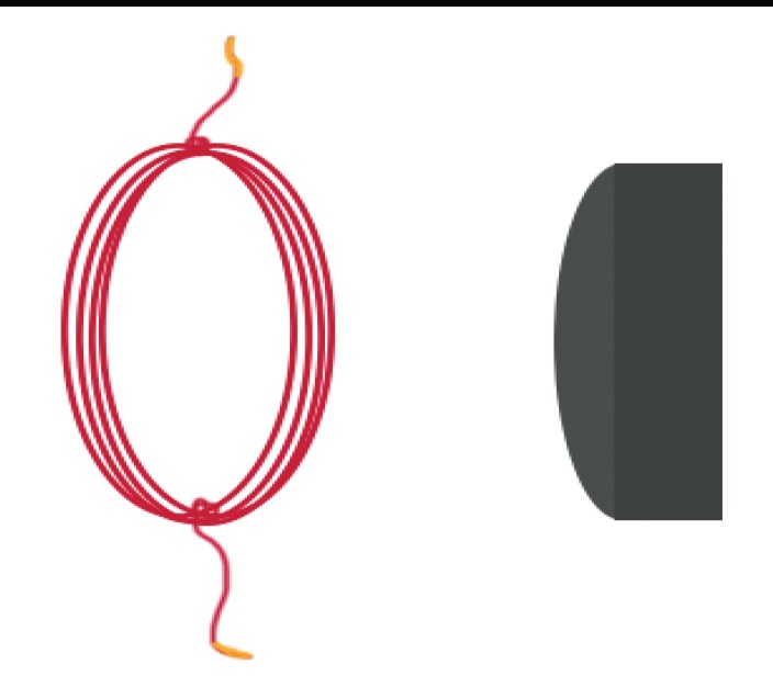
A compass aligns approximately with the local field subject to other interactions. Nearby current and magnetic materials can alter the pattern.
Pause and explain
Does a north magnetic pole mean positive electric charge?
Check your reasoning after answering
No. Magnetic poles and electric charges describe different properties and must not be substituted for each other.
Part 2 · Use magnetic force direction and magnitude
For a moving charge, magnetic force is F=q(v×B), with magnitude |q|vBsinθ. The cross product gives a perpendicular direction by the right-hand rule for positive q; a negative charge reverses it. Here velocity is right and field is out of the page, so positive-charge force is down. A stationary charge has no magnetic force in this simple expression, although an electric field can still act on it.
Read the visual model
Identify the labeled structures and units, then trace the arrows or compare values under the caption’s stated conditions. Separate the displayed evidence from a further inference. Write your reasoning before opening the guidance.
If the moving charge is negative, which way is its magnetic force in this diagram?
Visual reasoning — after your attempt
Up. Reversing q reverses the force from the positive-charge right-hand result.
For a moving charge, magnetic force magnitude is |q|vB sinθ and direction is perpendicular to velocity and field, with charge sign included. The magnetic force alone does no work on a point charge because it is perpendicular to instantaneous velocity. Electric forces can still transfer energy.
A charge moving parallel to a uniform magnetic field has zero magnetic force even though the field is present.
Pause and explain
Can a magnetic field alone speed up a point charge through this force?
Check your reasoning after answering
Not through the qv×B force alone; it can change direction but its perpendicular force does no work in this model.
Part 3 · Separate flux from field magnitude
Magnetic flux measures the field passing through an oriented surface. For a uniform field and flat area, ΦB=BAcosθ, where θ is between B and the area normal, not the surface itself. A loop can have nonzero field but zero net flux when its plane is parallel to B. Flux is measured in webers and differs from field strength in teslas. Changing field, loop area or orientation can change flux.
Read the visual model
Identify the labeled structures and units, then trace the arrows or compare values under the caption’s stated conditions. Separate the displayed evidence from a further inference. Write your reasoning before opening the guidance.
What flux results if B lies parallel to the loop plane?
Visual reasoning — after your attempt
Zero for a uniform field and flat loop, because θ=90° from the area normal.
Magnetic flux through a flat area is BA cosθ for a uniform field, with θ between field and the area’s normal. Flux changes if field, area, or orientation changes. A strong field does not necessarily give large flux through a surface oriented parallel to it.
Rotating a loop changes its area orientation and can change flux even with fixed B. A drawing should label the normal rather than the surface angle.
Pause and explain
Why can nonzero B give zero flux through a flat loop?
Check your reasoning after answering
If the field is perpendicular to the area normal, cosθ=0; the field lies along the surface rather than crossing it.
Part 4 · Use induction as a change and energy account
Electromagnetic induction produces an emf associated with changing magnetic flux: ε=−NΔΦB/Δt for the stated coil model. Emf is energy supplied per charge around a circuit; a current also needs a closed conducting path. Lenz’s law expresses the opposing sign: the induced response resists the flux change. Mechanical work or another external energy input supplies the electrical output, so a stationary magnet beside an unchanged coil does not provide endless electrical power.
Read the visual model
Identify the labeled structures and units, then trace the arrows or compare values under the caption’s stated conditions. Separate the displayed evidence from a further inference. Write your reasoning before opening the guidance.
A 100-turn coil changes flux per turn by 0.002 Wb in 0.10 s. Find average emf magnitude.
Visual reasoning — after your attempt
|ε|=100×0.002/0.10=2 V; its direction needs the geometry and sign convention.
Faraday’s law relates induced emf to flux-change rate, and Lenz’s law gives a direction opposing the change that produces it. An induced current requires a conducting path and depends on resistance and other circuit behavior. Induction does not supply unlimited energy without a source.
A changing-field or moving-loop arrangement needs an energy input account. The opposition implied by Lenz’s law is consistent with energy conservation.
Pause and explain
Does induced emf alone determine induced current?
Check your reasoning after answering
No. Current also depends on the circuit path, resistance, and dynamic behavior; an open loop can have emf without sustained closed-path current.
Apply the whole unit · Calculate an ideal induced emf
Illustrative 200-turn coil has flux per turn decrease uniformly from 0.00500 Wb to 0.00100 Wb in 0.100 s. Total closed-circuit resistance is 4.00 Ω; neglect inductive transients.
Your task
Find emf magnitude and approximate current, explain the Lenz-law direction qualitatively, and identify why a flux decrease alone does not specify clockwise versus counterclockwise.
What your response should show
- Define the system, quantities, units, and relevant conditions before selecting a model.
- Show intermediate calculations or a labeled evidence account, including signs or denominators.
- Explain how the supplied evidence supports the conclusion rather than reporting only an answer.
- Identify a meaningful uncertainty, model limit, or measurement needed to test the conclusion.
Response guidance — after your attempt
Flux change per turn is −0.00400 Wb over 0.100 s.
Emf magnitude=N|ΔΦ|/Δt=200×0.00400/0.100=8.00 V.
Approximate current magnitude=8.00/4.00=2.00 A.
The induced magnetic response tends to oppose the decrease in flux. A clockwise or counterclockwise label additionally needs the field direction, viewing side, and coil orientation. Current uses the stated resistance and negligible-transient approximation; an actual coil can need a fuller time-dependent account.
Scientific references and source-model foundations
- OpenStax — series and parallel circuits
- OpenSciEd 8.3 — forces at a distance
- OpenSciEd public middle-school figure license — CC BY 4.0
Parent / teacher teaching notes
Ask for the direction of the flux change before the current direction. Require a viewing convention and distinguish induced emf from a guaranteed current. Ask the learner to explain each symbol, axis, unit and arrow before calculating. Calculated examples, supplied illustrative records and actual historical observations are labeled separately. Selected public OpenSciEd middle-school source figures are foundation examples, not complete high-school editions or an endorsement; all advanced explanations are supplied locally.
The key idea
Currents produce magnetic fields; forces depend on vector geometry. Changing linked flux induces emf, while a current also requires an appropriate conducting path and energy input.
Force on a Current-Carrying Wire
F = BIL
F is force in newtons (N); B is magnetic field strength in tesla (T); I is current in amps (A); L is the length of wire in the field in meters (m).
Worked examples
Example 1
- For perpendicular current and field, F=BIL sin 90°=BIL.
- F = 0.4 × 5 × 0.2.
- = 0.4.
Example 2 · Worked application
- Parallel means θ=0°.
- sin 0=0, so the magnetic force is zero.
- Changing the direction to perpendicular would give maximum magnitude for the same q, v and B.
Zero force here does not mean no magnetic field.
Example 3
- A current is induced only when the magnetic field through the coil is *changing*, which happens while the magnet is moving in.
- Holding the magnet still means the field through the coil is no longer changing.
- With no change in the field, no voltage is induced, so the current — and the needle — falls back to zero.
Example 4 · Find and fix the mistake
- Test the claim against the stated conditions: Zero force here does not mean no magnetic field.
- The angle matters; use the vector cross-product direction and sinθ magnitude.
Zero force here does not mean no magnetic field.
Example 5 · Reason from the visual model
- Magnetic flux measures the field passing through an oriented surface. For a uniform field and flat area, ΦB=BAcosθ, where θ is between B and the area normal, not the surface itself. A loop can have nonzero field but zero net flux when its plane is parallel to B. Flux is measured in webers and differs from field strength in teslas. Changing field, loop area or orientation can change flux.
- Zero for a uniform field and flat loop, because θ=90° from the area normal.
Original tilted-area and normal schematic; arrow directions clarify angle definition rather than a numerical geometry.
Avoid these mistakes
- A static magnet beside a stationary coil does not continuously generate emf.
Check your understanding
What induces emf in a stationary coil?
Discuss the answer
A changing magnetic flux, through changing field, area, or orientation; a moving magnet can supply that change.
Return to the phenomenon
Return to the initial case. Why does moving a magnet relative to a coil matter? Revise your drawing or explanation using two named ideas and one stated limitation.
Compare explanations after your attempt
Changing flux induces emf; current requires closure and energy comes from the external change.
What should we investigate next?
Which comparison would test a remaining uncertainty? State what you would change, keep comparable and measure.
Investigate, calculate and revise
Keep a first model and an evidence-supported revision. Attempt each task before opening guidance; all required explanations and supplied-data routes are available locally.
Activity 1 · Return to the opening case
Use the opening phenomenon, unit definitions and explained Parts 1–4.
Your task
Return to the initial case. Why does moving a magnet relative to a coil matter? Revise your drawing or explanation using two named ideas and one stated limitation.
Success criteria
- Use the stated observations and appropriate units.
- Connect a labeled model with the physical/environmental mechanism.
- State assumptions and an evidence limitation.
- Explain a substantive revision or next test.
Hint
Keep object/material identity, material transfer and energy account distinct.
Response guidance — discuss after your attempt
Changing flux induces emf; current requires closure and energy comes from the external change.
Activity 2 · Transfer to a changed case
Cover the worked answer and use the explained models, relationships and notebook.
Your task
A charge+2 μC moves at 3.0×10⁴ m/s perpendicular to a 0.20 T field. Find magnetic force magnitude. What happens if velocity becomes parallel to the field?
Success criteria
- Use the stated measurements or conditions, with correct units.
- Connect the result to the physical or environmental mechanism or evidence relationship.
- Identify the assumption, model limit or further evidence requested.
Hint
Name known quantities and conditions, show intermediate steps and check conservation.
Response guidance — discuss after your attempt
F=|q|vB=0.012 N. Parallel motion gives sin 0=0 and zero magnetic-force magnitude in this model; electric forces would need a separate account.
Words to know
- magnetic field
- The region around a magnet or current where magnetic forces act, measured in tesla (T) and drawn with field lines from north to south.
- electromagnet
- A magnet created by running electric current through a coil of wire, often around an iron core, that can be switched on and off.
- electromagnetic induction
- The production of a voltage (and current) in a conductor by a changing magnetic field.
- electric motor
- A device that uses the force on a current-carrying wire in a magnetic field to convert electrical energy into motion.
- generator
- A device that uses electromagnetic induction to convert mechanical motion into electrical energy — essentially a motor run in reverse.
A twitching compass and an iron ring: the unification begins
In April 1820, Danish physicist Hans Christian Oersted was lecturing when he noticed a compass needle deflect every time he switched on a nearby electric current — the first hard evidence that electricity and magnetism are connected. Eleven years later, England's Michael Faraday wound two coils on opposite sides of an iron ring and found that switching current on or off in one coil induced a momentary current in the other, with nothing but the changing magnetic field connecting them. Oersted showed current makes magnetism; Faraday showed changing magnetism makes current. Together, these two discoveries opened the door to the electric age.
Magnetism is electricity seen in motion
Here is one of the strangest and most beautiful ideas in physics: electric and magnetic fields are not two separate things but two views of a single electromagnetic field, and which one you see depends on your motion. A stationary charge produces only an electric field; set it moving and a magnetic field appears alongside it. In fact, the magnetic force between two current-carrying wires can be re-described, from a frame moving with the charges, as an ordinary electric force — the two are linked by Einstein's special relativity. It's no accident that his landmark 1905 paper was titled 'On the Electrodynamics of Moving Bodies'; the deep unity of electricity and magnetism was one of the puzzles that led him straight to relativity.
Almost all the world's electricity is Faraday's induction
Step back and the scale of Faraday's 1831 discovery is staggering: the overwhelming majority of electrical energy generated on Earth comes from electromagnetic induction — spinning coils or magnets to induce a current. A coal or gas plant burns fuel only to boil water into steam whose single purpose is to spin a turbine; a nuclear plant uses fission heat to do the very same thing; hydroelectric dams and wind farms spin the turbines directly with moving water or air. In every case, the final step that actually makes the electricity is a magnet and a coil in relative motion. The notable exception is the solar panel, which makes current directly from light with no moving parts at all — but even it feeds into a grid built entirely around induction.
Motors, maglev, MRI, and the data on your hard drive
Once you can turn electricity into magnetism and back, electromagnetism quietly runs modern life. Electric motors — using the F = BIL force on a current-carrying coil — spin everything from kitchen blenders and washing machines to the wheels of electric cars. Maglev trains float and glide on carefully controlled electromagnets, eliminating wheel friction entirely. MRI scanners use enormous superconducting electromagnets to image the inside of your body without any radiation. And for decades, computer hard drives stored every file as microscopic patterns of magnetization, written and read by tiny electromagnetic heads. Behind each of these is the same two-way street Oersted and Faraday discovered: current makes magnetism, and changing magnetism makes current.
In the real world
Nearly all the world's electricity comes from generators: power plants spin turbines — with steam, wind, or falling water — to turn coils inside magnetic fields, using Faraday's induction to push current to your home.
Exit check
What induces emf in a stationary coil?
Check your explanation after answering
A changing magnetic flux, through changing field, area, or orientation; a moving magnet can supply that change.
Explain your reasoning without notes. If a key idea is missing, revisit the lesson and try again.
Electric Potential, Potential Energy & Capacitors
Learning goals
- I can distinguish electric potential, field, and potential energy.
- I can calculate capacitor charge and energy with unit-prefix conversions.
Readings for this unit
Before this unit
Charge, fields, work, signed numbers, and unit prefixes.
Use the detailed parent plan: two core 50–60-minute sessions per focused unit, with a third assigned for selected calculation/modeling topics. First study the core explanation and Parts 1–2 with their figures/checks; next study Parts 3–4, the whole-unit application, worked cases, varied practice and exit check. Attempt reasoning before opening guidance. Extend time when actual understanding requires it; investigations and chapter assessments have separate sessions.
Start with something to explain
How can a net-neutral capacitor store electrical energy?
Illustrative evidence case. Its two plates carry equal opposite charges at different potentials.
Notice and wonder
Record two observations using the stated quantities or relationships. Keep observations separate from possible causes. Write one question that a new measurement could help answer.
How can a net-neutral capacitor store electrical energy?
Your first model
Label each plate, Q magnitude, voltage and chosen energy boundary.
Build the language from the idea
- electric potential
- Electric potential energy per unit charge.
- capacitance
- Charge stored per potential difference in a linear model.
- equipotential
- A surface or set of points at equal electric potential.
Electric field is force per unit positive test charge: E=F/q. Electric potential is potential energy per unit charge, V=U/q, measured in joules per coulomb. A field is a vector, while potential is scalar. Voltage means potential difference between two locations, not a substance flowing through wire.
When a charge q moves across potential difference ΔV, its electric potential-energy change is ΔU=qΔV. Positive and negative charges respond differently to the same voltage sign. If the electric field alone does work, Welectric=−ΔU. An outside agent moving charge slowly can do positive work to increase U.
In an approximately uniform electrostatic field, potential decreases along the field: ΔV=−E·Δr. For a displacement distance d along the field, ΔV=−Ed and the magnitude is Ed. Equipotential surfaces have constant potential and are perpendicular to the local nonzero field. This simple relation must not replace a geometry-dependent nonuniform-field calculation.
A capacitor stores separated charge and energy. Capacitance C=Q/ΔV depends on geometry and dielectric material in a linear model; capacitance units are farads. Use Csymbol carefully because the letter C is also used for the coulomb unit. A simple parallel-plate model gives C=εA/d.
Stored capacitor energy is U=½C V²=½QV=Q²/(2C). The half arises because voltage rises as charge accumulates. Doubling voltage quadruples energy for fixed capacitance. Charge is not consumed when the capacitor releases energy; charges redistribute.
Use paper calculations with small unit scales. Capacitors from electronics can retain hazardous energy even after unplugging; do not dismantle appliances or discharge unknown equipment. A concept diagram provides the necessary model without handling stored-energy devices.
Build your understanding
Use the detailed parent plan: two core 50–60-minute sessions per focused unit, with a third assigned for selected calculation/modeling topics. First study the core explanation and Parts 1–2 with their figures/checks; next study Parts 3–4, the whole-unit application, worked cases, varied practice and exit check. Attempt reasoning before opening guidance. Extend time when actual understanding requires it; investigations and chapter assessments have separate sessions.
Part 1 · Distinguish potential from potential energy
Electric potential V is potential energy per charge relative to a chosen zero. For an electrostatic test-charge account, U=qV, so the same location can give different U for different q. Potential is a scalar and can be negative; field is a vector related to spatial change of potential. A midpoint of equal positive sources can have zero E but positive V relative to infinity. State the zero and avoid treating a potential value as a force.
Read the visual model
Identify the labeled structures and units, then trace the arrows or compare values under the caption’s stated conditions. Separate the displayed evidence from a further inference. Write your reasoning before opening the guidance.
What is U at A for a−2 C ideal test charge?
Visual reasoning — after your attempt
U=−2×5=−10 J relative to the same potential zero.
Electric potential is energy per charge at a position relative to a reference; potential energy depends on the charge placed in the field. For a change, ΔU=qΔV. Potential is a scalar while field is a vector, so a zero potential value does not itself imply zero field.
Changing the reference shifts potential values but leaves differences unchanged. A negative charge can lose potential energy while moving to a higher potential.
Pause and explain
Why can ΔU and ΔV have opposite signs?
Check your reasoning after answering
Because ΔU=qΔV and q can be negative; the charge sign determines how the potential difference affects its energy.
Part 2 · Link work and energy with signs
For electrostatic work, Wfield=−ΔU=−qΔV. A positive charge moving to lower potential loses electric potential energy while the field does positive work. A negative charge reverses this sign relationship for the same ΔV. If an external agent moves the charge slowly with negligible kinetic change, its work balances the field work. Specify the agent and motion conditions instead of saying “the work” without identifying which contribution is meant.
Read the visual model
Identify the labeled structures and units, then trace the arrows or compare values under the caption’s stated conditions. Separate the displayed evidence from a further inference. Write your reasoning before opening the guidance.
What field work acts on−2 C moving from 5 V to 2 V?
Visual reasoning — after your attempt
ΔU=(−2)(−3)=+6 J, so field work=−6 J.
For a fixed electrostatic field, work done by the field is −ΔU. An external agent moving a charge slowly may do the opposite work under suitable negligible-kinetic-change conditions. Name the actor before assigning a positive or negative work sign.
A positive charge moving to lower potential can gain kinetic energy if other transfers are negligible. A negative charge requires its sign in the same account.
Pause and explain
Does W=qΔV always mean work done by the electric field?
Check your reasoning after answering
No. The field’s work is −qΔV under this convention; +qΔV can describe the required external work in an appropriate slow transfer.
Part 3 · Treat capacitance as charge per voltage
A capacitor stores energy through separated opposite charges. Its capacitance C=Q/V uses the magnitude Q on either plate and the plate-to-plate potential difference, under a linear model. The entire ideal two-plate device can have zero net charge while each plate is charged. Farads are coulombs per volt. Geometry and dielectric material affect capacitance; doubling Q at fixed C doubles V rather than necessarily changing C itself.
Read the visual model
Identify the labeled structures and units, then trace the arrows or compare values under the caption’s stated conditions. Separate the displayed evidence from a further inference. Write your reasoning before opening the guidance.
For C=20 μF and V=12 V, what is plate charge magnitude?
Visual reasoning — after your attempt
Q=CV=240 μC, with equal opposite signs on the two ideal plates.
An ideal capacitor satisfies Q=CΔV, with equal-magnitude opposite charges on its plates. The symbol Q usually denotes one plate’s magnitude, not the net charge of both plates together. Capacitance depends on geometry and dielectric conditions, not simply the instantaneous stored charge.
A 2 μF capacitor at 12 V has 24 μC on each plate in magnitude, while the ideal pair’s net charge is zero.
Pause and explain
Can a capacitor store energy while having zero total net charge?
Check your reasoning after answering
Yes. Separated equal opposite plate charges create a field and energy store even when their total signed charge cancels.
Part 4 · Account for capacitor energy and real limits
For a linear capacitor, U=½CV²=Q²/(2C). The factor one half reflects that voltage rises as the capacitor charges; multiplying final voltage by final charge without the half overcounts the stored energy. Real capacitors have voltage ratings, leakage and losses, so the ideal equation is not permission to exceed a component’s limits. Here the 20 μF device at 12 V stores 1.44 mJ, a model calculation using supplied values.
Read the visual model
Identify the labeled structures and units, then trace the arrows or compare values under the caption’s stated conditions. Separate the displayed evidence from a further inference. Write your reasoning before opening the guidance.
What energy would the same ideal capacitor store at 6 V?
Visual reasoning — after your attempt
0.36 mJ, one quarter of the 12 V value.
An ideal capacitor stores U=½C(ΔV)²=½QΔV. The half factor reflects the changing voltage during charge buildup. Device voltage ratings, leakage, dielectric breakdown, and source behavior are separate practical constraints; a simple energy formula does not certify a suitable device.
Doubling voltage at fixed C quadruples stored energy, while doubling C at fixed voltage doubles it.
Pause and explain
Why is stored energy not simply Q times the final voltage?
Check your reasoning after answering
During charging, the voltage rises from zero to its final value; integrating the varying energy per charge gives the one-half factor for an ideal linear capacitor.
Apply the whole unit · Compare capacitor charge and energy
Illustrative ideal capacitance 2.00 μF is charged to 12.0 V; compare a final 24.0 V case with unchanged capacitance.
Your task
Calculate plate charge magnitude and stored energy in each case, explain their different scaling, and state what information is missing for deciding whether a real capacitor can operate at the higher voltage.
What your response should show
- Define the system, quantities, units, and relevant conditions before selecting a model.
- Show intermediate calculations or a labeled evidence account, including signs or denominators.
- Explain how the supplied evidence supports the conclusion rather than reporting only an answer.
- Identify a meaningful uncertainty, model limit, or measurement needed to test the conclusion.
Response guidance — after your attempt
At 12.0 V: Q=2.00×10⁻⁶×12=24.0 μC.
Energy=½×2.00×10⁻⁶×12²=1.44×10⁻⁴ J.
At 24.0 V: Q=48.0 μC and energy=5.76×10⁻⁴ J, four times larger.
The charge doubles while energy quadruples because they depend on voltage to different powers. Both values are ideal predictions. A real-component choice needs ratings, dielectric behavior, leakage, and circuit conditions. This supplied comparison is not an instruction to charge an unknown component.
Scientific references and source-model foundations
Parent / teacher teaching notes
Require microfarad conversion and a separate net-charge explanation. Use conceptual models rather than dismantling or charging unfamiliar electrical devices. Ask the learner to explain each symbol, axis, unit and arrow before calculating. Calculated examples, supplied illustrative records and actual historical observations are labeled separately. Selected public OpenSciEd middle-school source figures are foundation examples, not complete high-school editions or an endorsement; all advanced explanations are supplied locally.
The key idea
Voltage is energy per charge; capacitors store energy through separated charge.
Worked examples
Example 1
- ΔU=qΔV.
- 2×3.
Example 2 · Worked application
- ΔU=qΔV.
- ΔU=2.0×10⁻⁶×50=1.0×10⁻⁴ J.
- Positive charge moving to higher potential gains electric potential energy.
Potential is per charge; energy change also depends on q.
Example 3
- C=100×10⁻⁶F=.000100F.
- U=.5CV²=.5(.000100)(144).
Example 4 · Find and fix the mistake
- Test the claim against the stated conditions: Potential is per charge; energy change also depends on q.
- For negative q, ΔU=qΔV is negative for a positive ΔV.
Potential is per charge; energy change also depends on q.
Example 5 · Reason from the visual model
- A capacitor stores energy through separated opposite charges. Its capacitance C=Q/V uses the magnitude Q on either plate and the plate-to-plate potential difference, under a linear model. The entire ideal two-plate device can have zero net charge while each plate is charged. Farads are coulombs per volt. Geometry and dielectric material affect capacitance; doubling Q at fixed C doubles V rather than necessarily changing C itself.
- Q=CV=240 μC, with equal opposite signs on the two ideal plates.
Original ideal parallel-plate model; fringing fields and material details are omitted.
Avoid these mistakes
- Voltage does not flow; current is the rate of charge transfer.
Check your understanding
What does 9 V mean in energy terms?
Discuss the answer
A 9 V potential difference corresponds to 9 J of potential-energy change per coulomb, with sign depending on direction and charge.
Return to the phenomenon
Return to the initial case. How can a net-neutral capacitor store electrical energy? Revise your drawing or explanation using two named ideas and one stated limitation.
Compare explanations after your attempt
Charge separation creates the field/potential account; total net charge can be zero while stored energy½CV² is positive.
What should we investigate next?
Which comparison would test a remaining uncertainty? State what you would change, keep comparable and measure.
Investigate, calculate and revise
Keep a first model and an evidence-supported revision. Attempt each task before opening guidance; all required explanations and supplied-data routes are available locally.
Activity 1 · Return to the opening case
Use the opening phenomenon, unit definitions and explained Parts 1–4.
Your task
Return to the initial case. How can a net-neutral capacitor store electrical energy? Revise your drawing or explanation using two named ideas and one stated limitation.
Success criteria
- Use the stated observations and appropriate units.
- Connect a labeled model with the physical/environmental mechanism.
- State assumptions and an evidence limitation.
- Explain a substantive revision or next test.
Hint
Keep object/material identity, material transfer and energy account distinct.
Response guidance — discuss after your attempt
Charge separation creates the field/potential account; total net charge can be zero while stored energy½CV² is positive.
Activity 2 · Transfer to a changed case
Cover the worked answer and use the explained models, relationships and notebook.
Your task
A 50 μF capacitor is at 8 V. Find Q and U; compare U at 16 V in the same ideal model.
Success criteria
- Use the stated measurements or conditions, with correct units.
- Connect the result to the physical or environmental mechanism or evidence relationship.
- Identify the assumption, model limit or further evidence requested.
Hint
Name known quantities and conditions, show intermediate steps and check conservation.
Response guidance — discuss after your attempt
Q=400 μC; U=½×50×10⁻⁶×64=0.0016 J=1.6 mJ. At16 V, U=6.4 mJ, four times as much. Actual ratings must be separately respected.
Words to know
- electric potential
- Electric potential energy per unit charge.
- capacitance
- Charge stored per potential difference in a linear model.
- equipotential
- A surface or set of points at equal electric potential.
In the real world
Use the chapter investigation to connect this unit to measured evidence and a practical decision.
Exit check
What does 9 V mean in energy terms?
Check your explanation after answering
A 9 V potential difference corresponds to 9 J of potential-energy change per coulomb, with sign depending on direction and charge.
Explain your reasoning without notes. If a key idea is missing, revisit the lesson and try again.
Electrical Power, Energy & Circuit Design
Learning goals
- I can calculate component power and energy with correct circuit values.
- I can distinguish efficiency, kilowatt-hours, and source internal losses.
Readings for this unit
Before this unit
Current, voltage, resistance, series/parallel circuits, and time conversion.
Use the detailed parent plan: two core 50–60-minute sessions per focused unit, with a third assigned for selected calculation/modeling topics. First study the core explanation and Parts 1–2 with their figures/checks; next study Parts 3–4, the whole-unit application, worked cases, varied practice and exit check. Attempt reasoning before opening guidance. Extend time when actual understanding requires it; investigations and chapter assessments have separate sessions.
Start with something to explain
Why is the lowest wattage not enough to choose a useful design?
Illustrative evidence case. Two devices draw different power but must deliver the same agreed service.
Notice and wonder
Record two observations using the stated quantities or relationships. Keep observations separate from possible causes. Write one question that a new measurement could help answer.
Why is the lowest wattage not enough to choose a useful design?
Your first model
Define service, operating time, source limits and comparison boundary.
Build the language from the idea
- kilowatt-hour
- Energy delivered by 1 kW over 1hour, equal to 3.60MJ.
- internal resistance
- A simplified source resistance causing voltage drop and heating.
- emf
- Source energy per charge under the modeled open-circuit condition.
Electrical power is energy-transfer rate. For a component with voltage V and current I, P=VI. An ohmic resistor also gives P=I²R=V²/R because V=IR. A device’s actual resistance can depend on temperature; not every electronic component follows a constant-R model.
Electrical energy transferred over a constant-power interval is E=Pt. The kilowatt-hour is an energy unit: 1 kWh=1000W×3600 s=3.60×10⁶ J. It is not a kilowatt per hour. A household bill can be modeled from energy amount times a supplied price per kWh, but real tariffs include other charges.
In a series circuit, current is the same through components and voltage drops add; in parallel, each branch has the same potential difference and branch currents add. Power calculations must use each component’s own voltage or current, not indiscriminately the supply total.
Batteries have internal resistance. In a simple discharging model, terminal voltage V=emf−Irinternal, and internal heating is I²rinternal. A short circuit can cause a large current and dangerous heating; a battery is not an unlimited constant-voltage source at all loads.
A practical design specifies required function, maximum current, operating duration, and energy capacity. Efficiency compares useful output with electrical input. Different lamps can use different powers for similar useful illumination; comparison should specify light output and lifetime rather than watts alone.
Build only low-voltage circuits with an appropriate educational kit and adult guidance; never use wall sockets, improvised mains wiring, or short a battery. Heating-appliance examples below are paper problems. Circuit calculations do not substitute for equipment ratings or electrical installation knowledge.
Build your understanding
Use the detailed parent plan: two core 50–60-minute sessions per focused unit, with a third assigned for selected calculation/modeling topics. First study the core explanation and Parts 1–2 with their figures/checks; next study Parts 3–4, the whole-unit application, worked cases, varied practice and exit check. Attempt reasoning before opening guidance. Extend time when actual understanding requires it; investigations and chapter assessments have separate sessions.
Part 1 · Connect power to electrical quantities
Electrical power P=VI uses the voltage across and current through the same component at the same operating point. For an ohmic resistor, substituting V=IR gives I²R and V²/R. These are equivalent forms under that model, not independent laws for arbitrary devices. A larger resistance lowers power at fixed V but increases power at fixed I; the held-constant condition determines the comparison.
Read the visual model
Identify the labeled structures and units, then trace the arrows or compare values under the caption’s stated conditions. Separate the displayed evidence from a further inference. Write your reasoning before opening the guidance.
At fixed 12 V, what happens to power if resistance doubles from 24 to 48 Ω?
Visual reasoning — after your attempt
It halves from 6 to 3 W; current also halves.
For an appropriate steady circuit, electrical power transferred to a component is P=VI. Ohmic resistor forms I²R and V²/R follow by substitution. They are not interchangeable statements about a fixed real device under every source condition; identify what is held constant.
At fixed voltage, a larger ohmic resistance reduces power; at fixed current, a larger resistance increases it. The source condition changes the comparison.
Pause and explain
Why can resistance-power comparisons appear contradictory?
Check your reasoning after answering
They hold different variables constant. Use the actual source constraint before selecting P=V²/R or P=I²R.
Part 2 · Use energy units and duty cycle
A kilowatt-hour is an energy unit, not a power per hour:1 kWh=3.60×10⁶ J. Multiply power in kW by on-time in hours. A duty cycle is the fraction of a period during which a device operates in the specified mode, so a rated load running part-time uses less energy than continuous full-power operation. Include standby or multiple modes when they matter rather than multiplying a nameplate rating by every hour automatically.
Read the visual model
Identify the labeled structures and units, then trace the arrows or compare values under the caption’s stated conditions. Separate the displayed evidence from a further inference. Write your reasoning before opening the guidance.
What energy does a 2 kW load use at 25% duty over 8 h if off-state power is negligible?
Visual reasoning — after your attempt
2×0.25×8=4 kWh under the stated operating model.
Energy is power integrated over time; constant power gives E=PΔt. Kilowatt-hours measure energy, not power. A device’s maximum rated power is not necessarily its average use; duty cycle and operating behavior can change the total.
A 100 W device operating for 10 hours uses 1 kWh at constant power. A 50% on-off duty cycle over that interval changes the calculation.
Pause and explain
Why does a watt rating alone not determine daily energy use?
Check your reasoning after answering
Operating duration, duty cycle, and actual operating power are also needed.
Part 3 · Add loads within a stated source model
For ideal parallel loads sharing 12 V, source current is the sum of branch currents. Here 2+3+1=6 A and source output power is 72 W. A real source and conductors have operating limits and losses, so an ideal current sum is only part of a design comparison. Consider voltage regulation, continuous versus peak demand and the stated component ratings. Use supplied-data design here rather than modifying household wiring.
Read the visual model
Identify the labeled structures and units, then trace the arrows or compare values under the caption’s stated conditions. Separate the displayed evidence from a further inference. Write your reasoning before opening the guidance.
If one 3 A branch is switched off, what ideal total remains?
Visual reasoning — after your attempt
3 A and 36 W at unchanged 12 V, assuming the source maintains that voltage.
Parallel loads can be designed to share a source voltage, while total current is the sum of branch currents. Source capacity and wiring constraints need separate evidence. A proposed circuit should specify required service, branch behavior, and component ratings rather than just a total watt sum.
Two 12 V loads at 12 W and 6 W draw 1.0 A and 0.5 A under the ideal stated conditions.
Pause and explain
Does a supply voltage label establish sufficient capacity?
Check your reasoning after answering
No. Available current, power, regulation, and other ratings must be compatible with the loads.
Part 4 · Separate service efficiency and design evidence
A fair device comparison holds the delivered service comparable, such as an agreed illumination pattern and duration. Lower input power can reduce operational energy if the service is actually met, but lifespan, production, repair and disposal need a wider life-cycle account. An attractive label is not a substitute for measured performance. State criteria and constraints before selecting an option, then monitor whether the promised service and savings occur in use.
Read the visual model
Identify the labeled structures and units, then trace the arrows or compare values under the caption’s stated conditions. Separate the displayed evidence from a further inference. Write your reasoning before opening the guidance.
What is the operational energy difference over 2000 h for these options?
Visual reasoning — after your attempt
(12−8) W×2000 h=8000 Wh=8 kWh, for the same stated service and duration.
A useful comparison defines the same service and operating interval. Lower electrical input can reflect greater efficiency, reduced service, or a different duty cycle. Evaluate measured output alongside input, and retain uncertainty before selecting a design.
A lamp using fewer watts is not automatically better for a task if it provides insufficient illumination or a shorter service life.
Pause and explain
What makes an energy-saving comparison meaningful?
Check your reasoning after answering
Equivalent useful service, comparable conditions, duration, and relevant performance measures are needed in addition to input energy.
Apply the whole unit · Account for two ideal low-voltage loads
Illustrative regulated 12.0 V source supplies two parallel loads rated 12.0 W and 6.00 W at that voltage. Both operate 4.00 hours daily; neglect source losses.
Your task
Find branch and total current, daily energy, and required source power. Explain why an actual source choice still requires ratings and why a lower-power alternative needs a service comparison.
What your response should show
- Define the system, quantities, units, and relevant conditions before selecting a model.
- Show intermediate calculations or a labeled evidence account, including signs or denominators.
- Explain how the supplied evidence supports the conclusion rather than reporting only an answer.
- Identify a meaningful uncertainty, model limit, or measurement needed to test the conclusion.
Response guidance — after your attempt
Branch currents=P/V: 1.00 A and 0.500 A; total 1.50 A.
Total load power=18.0 W; daily energy=18.0×4.00=72.0 Wh=0.0720 kWh.
Ideal source must supply the 18.0 W load; actual source losses and ratings need a separate account.
The calculation uses ideal stated load behavior at 12 V and does not select a real supply. A lower-power replacement can reduce energy only if it still provides the required service under comparable use. Actual measured voltage, current, duty cycle, and source efficiency can change the input-energy budget.
Scientific references and source-model foundations
Parent / teacher teaching notes
Ask for an energy-versus-power unit check and equivalent service criteria. Keep the activity to supplied diagrams or approved enclosed low-voltage learning equipment. Ask the learner to explain each symbol, axis, unit and arrow before calculating. Calculated examples, supplied illustrative records and actual historical observations are labeled separately. Selected public OpenSciEd middle-school source figures are foundation examples, not complete high-school editions or an endorsement; all advanced explanations are supplied locally.
The key idea
Compute component power with its own voltage/current and distinguish watts from energy.
Worked examples
Example 1
- P=12×.50=6W.
- Time=600 s; E=6×600.
Example 2 · Worked application
- 60 W=0.060 kW; energy=0.060×5=0.30 kWh.
- 5 h=18000 s; E=60×18000=1.08×10⁶ J.
- The two forms agree using 1 kWh=3.6×10⁶ J.
Kilowatt-hour is energy, not power per hour.
Example 3
- E=1.2×2=2.4 kWh.
- Cost=2.4×.20.
Example 4 · Find and fix the mistake
- Test the claim against the stated conditions: Kilowatt-hour is energy, not power per hour.
- A kWh is a unit of energy; watts and kilowatts measure power.
Kilowatt-hour is energy, not power per hour.
Example 5 · Reason from the visual model
- For ideal parallel loads sharing 12 V, source current is the sum of branch currents. Here 2+3+1=6 A and source output power is 72 W. A real source and conductors have operating limits and losses, so an ideal current sum is only part of a design comparison. Consider voltage regulation, continuous versus peak demand and the stated component ratings. Use supplied-data design here rather than modifying household wiring.
- 3 A and 36 W at unchanged 12 V, assuming the source maintains that voltage.
Calculated ideal branch demand; no household electrical work is part of this exercise.
Avoid these mistakes
- Watts measure power; watt-hours and joules measure energy.
Check your understanding
How would you compare two lamp designs fairly?
Discuss the answer
Compare equal useful light output, energy over the same use, lifetime, and relevant disposal or cost assumptions.
Return to the phenomenon
Return to the initial case. Why is the lowest wattage not enough to choose a useful design? Revise your drawing or explanation using two named ideas and one stated limitation.
Compare explanations after your attempt
Power and time determine energy; a good design also tests performance, durability and impacts under transparent criteria.
What should we investigate next?
Which comparison would test a remaining uncertainty? State what you would change, keep comparable and measure.
Investigate, calculate and revise
Keep a first model and an evidence-supported revision. Attempt each task before opening guidance; all required explanations and supplied-data routes are available locally.
Activity 1 · Return to the opening case
Use the opening phenomenon, unit definitions and explained Parts 1–4.
Your task
Return to the initial case. Why is the lowest wattage not enough to choose a useful design? Revise your drawing or explanation using two named ideas and one stated limitation.
Success criteria
- Use the stated observations and appropriate units.
- Connect a labeled model with the physical/environmental mechanism.
- State assumptions and an evidence limitation.
- Explain a substantive revision or next test.
Hint
Keep object/material identity, material transfer and energy account distinct.
Response guidance — discuss after your attempt
Power and time determine energy; a good design also tests performance, durability and impacts under transparent criteria.
Activity 2 · Transfer to a changed case
Cover the worked answer and use the explained models, relationships and notebook.
Your task
A 15 W device is replaced by a 9 W device providing the same service for 2500 h/year. Find annual energy saved in kWh and joules, and name one uncounted life-cycle term.
Success criteria
- Use the stated measurements or conditions, with correct units.
- Connect the result to the physical or environmental mechanism or evidence relationship.
- Identify the assumption, model limit or further evidence requested.
Hint
Name known quantities and conditions, show intermediate steps and check conservation.
Response guidance — discuss after your attempt
Saving=(0.015−0.009)×2500=15 kWh=5.40×10⁷ J/year. Production, transport, replacement lifespan or disposal is outside this operational-only result.
Words to know
- kilowatt-hour
- Energy delivered by 1 kW over 1hour, equal to 3.60MJ.
- internal resistance
- A simplified source resistance causing voltage drop and heating.
- emf
- Source energy per charge under the modeled open-circuit condition.
In the real world
Use the chapter investigation to connect this unit to measured evidence and a practical decision.
Exit check
How would you compare two lamp designs fairly?
Check your explanation after answering
Compare equal useful light output, energy over the same use, lifetime, and relevant disposal or cost assumptions.
Explain your reasoning without notes. If a key idea is missing, revisit the lesson and try again.
Problem 1
Answer and explanation
0.9 N
F = kq₁q₂/r² = (9 × 10⁹)(1 × 10⁻⁶)(1 × 10⁻⁶) ÷ (0.1)² = (9 × 10⁻³) ÷ 0.01 = 0.9 N. Since the charges have the same sign, the force is repulsive.
Problem 2
Answer and explanation
They repel — like charges repel.
Both rods carry the same sign of charge (positive), and the rule for electric charge is that like charges repel while opposite charges attract. So the two positively charged rods push apart.
Problem 3
Answer and explanation
1.5 × 10⁵ N/C (150,000 N/C)
E = F ÷ q = 0.6 ÷ (4 × 10⁻⁶) = 150,000 N/C, or 1.5 × 10⁵ N/C.
Problem 4
Answer and explanation
3 A
I = Q ÷ t = 24 ÷ 8 = 3 A.
Problem 5
Answer and explanation
12 V
V = W ÷ Q = 60 ÷ 5 = 12 V.
Problem 6
Answer and explanation
The longer wire has the greater resistance.
Resistance increases with length, because charge must push through more material and undergo more collisions. Doubling the length roughly doubles the resistance (R is proportional to length), so the longer wire resists current more.
Problem 7
Answer and explanation
3 A
By Ohm's law, I = V ÷ R = 9 ÷ 3 = 3 A.
Problem 8
Answer and explanation
Total resistance = 10 Ω; current = 2 A
In series, resistances add: R = 2 + 3 + 5 = 10 Ω. Then Ohm's law gives the current: I = V ÷ R = 20 ÷ 10 = 2 A (the same current flows through all three).
Problem 9
Answer and explanation
3 Ω
1 ÷ R = 1/6 + 1/6 = 2/6 = 1/3, so R = 3 Ω. For two equal resistors in parallel, the total is always half of one.
Problem 10
Answer and explanation
The meter shows a current whenever the magnet is moving; this is electromagnetic induction.
While the magnet moves, the magnetic field through the coil is changing, which induces a voltage and drives a current (the needle deflects). Pushing the magnet in and pulling it out send current in opposite directions. When the magnet is held still, the field stops changing and the current stops. This production of current by a changing magnetic field is electromagnetic induction, discovered by Faraday.
Problem 11
Answer and explanation
0.72 N
F = BIL = 0.3 × 6 × 0.4 = 0.72 N. This is the force that makes an electric motor's coil turn.
Problem 12
Answer and explanation
24 W
P = IV = 2 × 12 = 24 W.
Problem 13
Answer and explanation
Current = 4 A; power = 960 W
Current: I = V ÷ R = 240 ÷ 60 = 4 A. Power: P = IV = 240 × 4 = 960 W. (You can check with P = V²/R = 240² ÷ 60 = 57,600 ÷ 60 = 960 W.)
Problem 14
Answer and explanation
F=qE=.002N along the field; a negative charge would reverse direction.
Response criteria
- State a scientifically accurate conclusion.
- Show the calculation or mechanism that supports it.
- Include units, conditions, or limits where relevant.
Problem 15
Answer and explanation
F=qE gives+0.0010 N east for+2 μC and−0.0015 N, i.e.west, for−3 μC. The field is unchanged in the ideal nonperturbing-test model.
F=qE gives+0.0010 N east for+2 μC and−0.0015 N, i.e.west, for−3 μC.
The field is unchanged in the ideal nonperturbing-test model.
Response criteria
- Use the stated measurements or conditions, with correct units.
- Connect the result to the physical or environmental mechanism or evidence relationship.
- Identify the assumption, model limit or further evidence requested.
Problem 16
Answer and explanation
I=Q/t=3 A; conventional current direction is positive-charge flow.
Response criteria
- State a scientifically accurate conclusion.
- Show the calculation or mechanism that supports it.
- Include units, conditions, or limits where relevant.
Problem 17
Answer and explanation
I=9/12=0.75 A; P=VI=6.75 W; E=Pt=270 J. The stated constant resistance and voltage must persist over the interval.
I=9/12=0.75 A; P=VI=6.75 W; E=Pt=270 J.
The stated constant resistance and voltage must persist over the interval.
Response criteria
- Use the stated measurements or conditions, with correct units.
- Connect the result to the physical or environmental mechanism or evidence relationship.
- Identify the assumption, model limit or further evidence requested.
Problem 18
Answer and explanation
1/R=1/6+1/6=1/3, soR=3ohm; lower than either branch.
Response criteria
- State a scientifically accurate conclusion.
- Show the calculation or mechanism that supports it.
- Include units, conditions, or limits where relevant.
Problem 19
Answer and explanation
Currents are3 A and1 A; total4 A. Req=12/4=3 Ω and P=12×4=48 W. Branch powers36 W and12 W sum consistently.
Currents are3 A and1 A; total4 A.
Req=12/4=3 Ω and P=12×4=48 W.
Branch powers36 W and12 W sum consistently.
Response criteria
- Use the stated measurements or conditions, with correct units.
- Connect the result to the physical or environmental mechanism or evidence relationship.
- Identify the assumption, model limit or further evidence requested.
Problem 20
Answer and explanation
A changing magnetic flux, through changing field, area, or orientation; a moving magnet can supply that change.
Response criteria
- State a scientifically accurate conclusion.
- Show the calculation or mechanism that supports it.
- Include units, conditions, or limits where relevant.
Problem 21
Answer and explanation
F=|q|vB=0.012 N. Parallel motion gives sin0=0 and zero magnetic-force magnitude in this model; electric forces would need a separate account.
F=|q|vB=0.012 N.
Parallel motion gives sin0=0 and zero magnetic-force magnitude in this model; electric forces would need a separate account.
Response criteria
- Use the stated measurements or conditions, with correct units.
- Connect the result to the physical or environmental mechanism or evidence relationship.
- Identify the assumption, model limit or further evidence requested.
Problem 22
Hints
Write the relationship first; substitute with consistent units.
Answer and explanation
0.01 C
Q=CV=.010.
Problem 23
Answer and explanation
Voltage grows during charging; average charging voltage is half final voltage for a linear capacitor.
Response criteria
- State a scientifically accurate conclusion.
- Show the calculation or mechanism that supports it.
- Include units, conditions, or limits where relevant.
Problem 24
Answer and explanation
Q=400 μC; U=½×50×10⁻⁶×64=0.0016 J=1.6 mJ. At16 V, U=6.4 mJ, four times as much. Actual ratings must be separately respected.
Q=400 μC; U=½×50×10⁻⁶×64=0.0016 J=1.6 mJ.
At16 V, U=6.4 mJ, four times as much.
Actual ratings must be separately respected.
Response criteria
- Use the stated measurements or conditions, with correct units.
- Connect the result to the physical or environmental mechanism or evidence relationship.
- Identify the assumption, model limit or further evidence requested.
Problem 25
Hints
Write the relationship first; substitute with consistent units.
Answer and explanation
3000 J
E=Pt.
Problem 26
Answer and explanation
Very low external resistance permits large current; internal resistance then dissipates substantial I²r heat.
Response criteria
- State a scientifically accurate conclusion.
- Show the calculation or mechanism that supports it.
- Include units, conditions, or limits where relevant.
Problem 27
Answer and explanation
Saving=(0.015−0.009)×2500=15 kWh=5.40×10⁷ J/year. Production, transport, replacement lifespan or disposal is outside this operational-only result.
Saving=(0.015−0.009)×2500=15 kWh=5.40×10⁷ J/year.
Production, transport, replacement lifespan or disposal is outside this operational-only result.
Response criteria
- Use the stated measurements or conditions, with correct units.
- Connect the result to the physical or environmental mechanism or evidence relationship.
- Identify the assumption, model limit or further evidence requested.